|
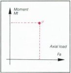
P = ƒ
(Fa, Mt) Fa = Axial load x Ka Mt = Moment x Ka |
| Rollix - Selecting a Slewing Ring |
|
I - BEARING CAPACITY
It is necessary to choose the slewing ring by comparing the loads and/or stresses associated with the intended application with the characteristics of a known slewing ring.
As the case may be:
When there is no dimensional requirement, the optimal ring for this use will be selected according to the load requirements.
When there are dimensional constraints (diameter, module, weight, etc.) the suitability of the slewing ring considered will be verified and its life calculated.
The load curves are calculated according to the ability of the ring considered to handle the loads shown on the coordinate axes, and this as a function of:
Its geometric envelope,
The type of steel used,
The heat treatment,
The type of rolling elements, etc.
The contact parameters of the rolling elements.
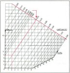
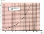
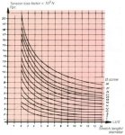
GRAPHIC REPRESENTATION
The capacities of the slewing rings are represented graphically by two basic curves:
LIMIT CURVE (L)
- This curve shows the maximum capacity of the ring.
- The "LIMIT" curve represents the maximum values that must never be exceeded even in the case of test loads or of occasional overloading.
UTILIZATION CURVE (U)
- This curve is derived from the max. curve and represents the maximum allowable working values for applications where this maximum load is only occasionally achieved.
- Expected lifetime: 50,000 cycles max.
- In the case where the maximum working load is regularly achieved, the ring selection must be based on the application factors that follow.The capacity graph for standard slewing rings shown on page 38 onwards are the limit curves (L) having gear type 770 where applicable.
Some graphs are shown doffed to improve the presentation.
BEARING APPLICATION FACTORS
In order to recommend a slewing ring destined for a specific use, it is necessary to ensure proper strength of the race-way by comparing the operating loads in relation to the capacity of the ring chosen or to be determined. This comparison furthermore makes it possible to have an idea of the lifetime of the slewing ring; but the latter can only be calculated for working stresses and not for occasional stresses due to brief and irregular overloading nor for equipment acceptance testing.
TEST LOADS
- These loads may not be considered as a "fatigue".
- These loads must be taken into consideration as determined by the customer, without applying any utilisation - coefficients or factors given developed by ROLLIX.
| IN ALL CASES THE
REPRESENTATIVE POINT OF THESE LOADS MUST NOT EXCEED "LIMIT" CURVE OF THE SELECTED OR RECOMMENDED SLEWING RING. |
WORKING LOADS
- These loads constitute the "fatigue" element of the slewing ring.
The graphic representation of the points characterising the operating loads must, in conformity with the parameters defined in the computer calculation files, take into consideration the particular utilisation - coefficients of each user and the lifetime and speed adjustments factors given by the graphs. This is the case of a special rather than a standard use.
- Point located above "LIMIT" curve: life-time < 6000 H
- Point located on "LIMIT" curve: life-time = 6000 H
- Point located under "LIMIT" curve: life-time > 6000 H1 - GENERAL FORMULA
Given P representative point of the working loads
With Px: origin on the axial loads axis
Py: origin on the moments axis.
General Formula
| Px = Fa x (Ka x Kv x Kt) |
| Py = Mt x (Ka x Kv x Kt) |
With
Ka: utilisation - coefficient
Ky: lifetime adjustment factor
Kt: speed adjustment factor2 - STANDARD APPLICATION
Corresponds to the uses listed in the so-called "standard" applications table for which the values given assume the following:
- Lifetime: 6000 hours
- Average speed: indicated in the table.
In this case the general formula becomes:
| Px = Fa x Ka |
| Py = Mt x Ka |
|
This is due to the fact that for 6000 hours and that Ky is already incorporated in Ka |
Kt = 1 |
However note that the average speed indicated is statistically derived from the maximum speed according to the formula:
| Vmv = Vmax x 0,06 | (slewing ring with spacer) |
| Vmv = Vmax x 0,50 | (slewing ring with cage) |
3 - SPECIFIC APPLICATIONS
In this case it is not possible to use the simplified formula since the speed and/or the real lifetime associated with the utilization are different from the parameters taken into consideration in the table of standard applications.
The formula used to determine the origins of the points P is used instead of the simplified formula since the speed and lifetime factors must be adjusted.
In this case:
Kt: directly provided by the lifetime graph
Kv: correction factor to be calculated from speeds graph.
| Kv = | Kv real |
| Kv standard |
therefore:
| Px = Fa x | (Ka x Kvr x Kt) |
| Kvs | |
| Py = Mt x | (Ka x Kvr x Kt) |
| Kvs |
Standard case
|
|
P = ƒ
(Fa, Mt) Fa = Axial load x Ka Mt = Moment x Ka |
In the case where the application has a radial load as well, it is necessary to convert this radial load into an equivalent axial load:
Horizontal slewinq ring - vertical axis
|
Fa equ = Fa + (Ki x Fr) |
| Ki = f | [ | Fr , Mt | ] |
| Fa mFa |
Vertical slewing ring - horizontal axis
Fa equ = Fa + 1,2(Ki x Fr)Where
Fa = axial loads (N)
Fr = radial load (N)
Mt = bending moment (Nm)
= average diameter of the ring (m)Examples:
|
|
} | from which Ki = 0,65 (see graph) |
Therefore Fa equ = 10 + (0,65 x 20) = 23T
APPLICATION FACTORS
(Established for a lifetime of 6000 hours.)
| MACHINE | Average speed Rpm |
Application factors Ka |
MACHINE | Average speed Rpm |
Application factors Ka |
| Armament turret | 1.5 | 1.5 | Mobile telescopic crane | 1 | 1.65 |
| Bucket | 1.5 | 1.65 | Offshore crane | 1 | 1.8 |
| Cable shovel | 2 | 1.65 | Post jib crane | 1 | 1.35 |
| Compactor | 2.5 | 1.80 | Railway crane | 1 | 1.50 |
| Concrete mixer | 5 | 2.40 | Rapid rotation radar | 5 | 2 |
| Concrete pump | 1.5 | 1.65 | Rapid rotation scanner | 3.5 | 1.65 |
| Dragline | 1.5 | 1.65 | Robotics | 3.5 | 1.65 |
| Dock crane | 1 | 1.65 | Service dock crane | 0.8 | 1.35 |
| Fairlead | 0.8 | 1.35 | Settler (water and sewage treatment) | 0.6 | 1.35 |
| Fork-lift truck | 1 | 1.35 | Slow rotation radar | 1 | 1.35 |
| Fork-lift wheel | 1.5 | 1.50 | Slow rotation radiology | 1.00 | 1.35 |
| Grabbing crane | 1.5 | 1.80 | Tower crane, slewing jib type | 1.5 | 1.65 |
| Heavy winch | 2 | 1.65 | Tower crane, slewing tower type | 1.5 | 1.80 |
| Hydraulic lift platform | 1 | 1.50 | Track hook crane | 1.5 | 1.80 |
| Hydraulic shovel | 2.5 | 2 | Truck crane | 1 | 1.50 |
| Loading dock crane | 1 | 1.65 | Turntable | 1 | 1.35 |
| Merry-go-round | 5 | 2.40 | Vibrating compactor | 2.5 | 2 |
| Mine digging machinery | 1.5 | 2.00 | Welding positionner | 0.8 | 1.35 |
| Mobile fixed boom crane | 1 | 1.5 | Windmill | 0.8 | 1.65 |
| Mobile grapple crane | 1 | 1.80 |
These factors are determined statistically and are based on a large number of observations for each type of application. The standard parameters retained are as follows:
Lifetime: 6000 hours
Average speed indicated: 0.6 x max. speed
Work under normal weather conditions
Conventional application (and not specific)
Attention: The speed factor is not the same for all applications. It might be necessary to determine the speed corrective factor:
Ky real from the corresponding curve Ky standard THE "LIFETIME" CORRECTION FACTOR
For an application whose lifetime is different than that indicated in page 15.
ROLLIX slewing rings are normally designed for a minimum lifetime of 6000 hours of operation :This capacity and this lifetime are represented on the particular curves of each ring by the "Limit" curve.
A precise estimate of the real lifetime can be made using the graph shown below, if, however, all of the other parameters used in determining the application point have been respected.
| Kt = | Ring Capacity | = | Limit curve moment |
| Capacity Used | Application point moment |
METHODOLOGY
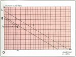
Given a ring having a "Limit" capacity of L
Given P which represents the real utilisation characteristics of the user:
bearing load (Fa - Fr - Mt)
average rotation speed.
Lifetime correction factor
| Kt = | OL |
| OB |
B is projection parallel to L of P.
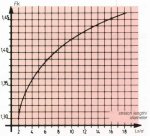
Since Kt is known, the graph 2 back gives with sufficient accuracy the lifetime in terms of hours and operation.
NOTE:
In the case where operation cycle(c) of the machine is given, it is necessary to calculate the lifetime of each cycle; the total lifetime is therefore:
| LT = | 100 | ||||||
| C1 | + | C2 | + | C3 | + ... + | Cn | |
| L1 | L2 | L3 | Ln | ||||
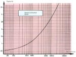
THE SPEED CORRECTION FACTOR
For applications where the speed required is different from that indicated (See Application Factors)
The speed of rotation of a slewing ring is an important factor where the lifetime of the ring is concerned. It is therefore necessary to take this parameter into consideration in order to determine or to check a ROLLIX ring, by applying a speed correction factor to the load data (see graph below)
- However the speed to be considered is the average speed of rotation:
|
Vav = Vmax x 0.60 |
In the case of a special type of ring with a bearing cage the average speed is:
|
Vav = Vmax x 0.50 |
APPLICATION EXAMPLES
DETERMINATION OF A SLEWING RING FOR A TOWER CRANE - SLEWING JIB TYPE.
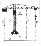
| CUSTOMER'S DATA: | P = 3T (30,000N) | l = 20m | |
| Q = 6T (60,000N) | q = 9m | ||
| F1 = 3T (30,000N) | f1 = 10m | ||
| F2 = 2T (20,000N) | f2 = 4m | ||
| M = 1T (10,000N) | |||
| LOAD CALCULATIONS: | |||
| Fa = Q + P + F1 + F2 + M = 15T (150,000N) | |||
| Mr = (F1 x f1) + (P x l) - (F2 x f2) - (Q x q) = 28T x m =280,000N x m | |||
|
|||
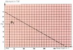
ASSUMPTION 1: Case of standard use
Lv = 6,000 hours
Vav = 1 RpmDetermining the application point P1
Application coefficient for a high-tower crane: 1.65 (Ka)
{ P1 (x) = Fa x 1.65 = 24.75 T (247,500N) P2 (y) = Mr x 1.65 = 46.2 Tm (462,000Nm) The ring having the load curve opposite is suitable since the application point P1 is located under the limit curve.
ASSUMPTION 2:
Lv = 16.000 hours Vav: 2,3 Rpm
Determining the application point P2
- corrective factor for Vav of 2,3 Rpm = 1.36
- corrective factor for Vav of 1 Rpm = 1
- corrective factor for Lv of 16.000 hours = 1.4
P2 (x) = 15 x 1,36 x 1.65 x 1.4 = 47.25 T (472,500N)
1 P2 (y) = 28 x 1,36 x 1.65 x 1.4 = 88.2 Tm (882,000Nm)
1 The ring having the load curve opposite is suitable since the application point P2 is located under the curve.
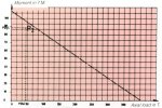
ASSUMPTION 3: Vav of 1,6 Rpm
The ring having been selected, we would now like to determine its life
Determining the application point P3
corrective factor for Vav of 1,6 Rpm = 1.18
P3 (x) = Fa x 1,18 x 1.65 = 29.25 T (292,500 N)
1 P3 (y) = Mr x 1,18 x 1.65 = 54.6 Tm (546,000 Nm)
1
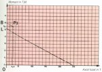
Point P3 is located above the limit curve
The lifetime corrective factor is:
Kv = OL/OB = 52/60 = 0.86After consulting the curve below, we find that the lifetime is 3,800 hours.
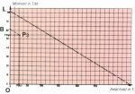
Point P3 is below the limit curve
The lifetime corrective factor is:
Kv = OL/OB = 82/62 = 1.32By consulting the curve below, we find that the lifetime is 14,000 hours.

II - DETERMINE THE GEAR TYPE
ROLLIX DEFONTAINE make several types of gears and can offer either the alone, or the "ring + pinion" or worm drive in the following forms:
| Spur gear | : |
exterior or interior normal or corrected |
| Helical gear | : |
exterior only pinion (or worm drive) |
| Special gear | : |
tangential torque chain wheel, etc. |
The great majority of slewing rings fall into the spur gear ring (or parallel) category.
Most of the Rollix slewing ring have a great correction. It is also recommended to correct the pinion by positive offsetting which will modify the distance between the axes.
Gear correction makes it possible to considerably improve the operating and meshing characteristics:
- suppression of interference,
- increasing the tensile strength,
- improving the surface pressures,
- improving sliding, etc.It should be noted that the contact ratio will be slightly decreased in the case of corrected gears.

Z1 = number of teeth on pinion
Z2 = number of teeth on wheel
Σ δ = δ1 + δ2
where
δ1 = pinion correction factor
δ2 = wheel correction factor.TOOTH FORM PRECISION
In the case where no quality class is required by the customer or indecated on the drawings, ROLLIX DEFONTAINE manufactures the slewing rings according to the standard DIN or AFNOR quality as follows:
GEAR NOT SURFACE HARDENED
| DIN class |
AFNOR class |
Max. |
Module maxi. |
Observations |
| 12 | 12 | all sizes |
25 | module 45 pitch with special machinery |
| 10-11-12 | 11-10-9 | all sizes |
20 | |
| 9-10 | 8-9 | 3100 | 22 | special machinery |
| 7-8 | 7 | 2500 | 20 | upon request |
SURFACE HARDENED GEARS
- in general, by surface tempering for approx. 55HRc
- The classes of gear mentioned above are therefore shifted and specifications cannot be then maintained, but Rollix is able to respect AFNOR and DIN classes 10-11-12.In the case where it is imperative to obtain a higher quality of gear (class 5 or 6), such quality can only be obtained by grinding the gear (consult our design office).
|
IMPORTANT It is useful to point out that in the above tables, ROLLIX DEFONTAINE means by the respecting of a quality class, the respecting of all of the parameters characterizing a gear as indicated in the AFNOR and DIN documents. Because of this, and in the case where the customer's requirements concern not all of the parameters but only one or two, ROLLIX DEFONTAINE can assure higher qualities. |
III - FASTENER SELECTION
The standard bolting arrangement proposed is designed to suit the capacity of the ring.
Specific bolting patterns are available and can be designed for the application on demand.
Calculating the number of bolts required is carried out using the formula shown on page 22 based on the loads to be applied. In all cases it is assumed that the ring is supported and is not unslung.
The ISO standard has defined a bolt and assembly elements classification. According to this standard and also calculations based on the specificion VDI 2230. ROLLIX DEFONTAINE recommends for its slewing rings, the use of high tensile bolts and studs, the classes, descriptions and tightening requirements of which are given below.
SCREW AND STUD CLASSIFICATION
The quality classes of screws and studs are designated by a symbol consisting of two numbers separated by a point. Multiplying these two numbers together will give the approximate yield strength of the screws or studs used. For the attachment of slewing rings, ROLLIX-DEFONTAINE recommends the use of the following classes of bolts.
| GRADE (ISO) | MECHANICAL PROPERTIES | |||
| Description | Strength in N/mm2 | Elongat. | ||
| tensile | yield | fatigue | % | |
| 8.8 | 800 | 640 | 200 | 12 |
| 10.9 | 1000 | 900 | 277 | 11 |
| 12.9 | 1200 | 1080 | 338 | 9 |
NUT CLASSIFICATION
The quality classes of nuts are designated by a grade number.
The grades indicated by ISO are:
Classes: 4 - 5 - 6 - 8 - 10 - 12.For the attachment of slewing rings, ROLLIX DEFONTAINE recommends the use of high-strength nuts, the grade of which depends upon the grade of the screws.
| NUTS | USE WITH SCREWS | ||
| Grade | Specific stress N/mm2 |
Normal pitch grade |
Fine pitch grade |
| 8 | 800 | 8.8 | 6.9 |
| 10 | 1000 | 10.9 | 8.8 |
| 12 | 1200 | 12.9 | 10.9 |
DESIGNATION
Bolt designation is to specify all the main characteristics of the thread and nut:
Shape of the head
Diameter
Length
Finishing code symbol
Quality class.
To ensure satisfactory bolting down of their slewing rings, ROLLIX DEFONTAINE recommend the use of:
- Hexagonal head bolts code H
- Square head bolts code QMoreover, the surface finish of the bolt heads must meet the requirements of a semi fine class, code T.
Example reference: Bolt HM 18 - 90 1 - Class 10.9.
SELECTION OF THE MOUNTING BOLTS
To ensure that the slewing ring is correctly and efficiently clamped down, the following parameters must be taken into consideration:
number of bolts
class and quality of the bolts
necessary clamping force
bolt head, bearing and seating surfaces must be machined and must comply with our specifications regarding supports and surface finish.
number of bolts and screws must be sufficient not only to ensure good fitting but also to avoid any deformation of external and internal rings. It must correspond to the number of fixing holes which are in the ring.
CALCULATION CONDITIONS
equidistant bolts; ie. equally positioned on the pitch circle.
slewing rings and supports in steel.
rigid structure.
slewing ring bolted directly to its support without using plastic cement.
use of centring spigots; in this case, there is practically no shear loads on the bolts.
high tensile bolts.
calculations based on the ring having the most heavily stressed bolts.
calculations carried out on the fixed ring are the most usual.
TIGHTENING STRESS - TIGHTENING TORQUE
It this table, the tightening tension is equal to 80% of the elastic limit. (coefficient of friction: 0.12 to 0.16)
|
IMPORTANT OBSERVATIONS The
most effective attachment is obtained by using bolts (screw and nut) since
the tightened length is longer in this case and the tension losses are
minimal. In the case of attachment with studs (in either the support or the ring) the setting depth of the screw (t) must be:
generally, t > 1.5 x screw |
CALCULATING THE BOLTS AND NUTS:
- Determine the number of bolts
Known loads
Ring selected
Bolt class selected
N = 1,6 x Fk [4 x Mt - Fa x D] D x [Ts - Fpc]
| - N | : Number of bolts theoretically necessary | |
| - D | : Pitch circle diameter of holes | - m |
| - Mt | : Bending moment | - N.m |
| - Fa | : Axial load | - N |
| - Ts | : Tightening tension | - N |
| - Fk | : Bolt stretch length coefficient | |
| - Fpc | : Loss of tension due to size of the bolt | - N |
| - t | : Setting depth of the stud | mm |
- Determining the stretch length coefficient Fk:
This coefficient not only takes into consideration the dimensions of the bolt but also the type of the slewing ring.
The diagram below directly indicates the value Fk as a function of the Ls/d
- Determining the loss of tension Fpc:
This parameter takes into consideration the dimensions of the bolt.
Ratio of stretch length to diameter
Diameter of the attachment bolt
The values of Fpc are directly given in the table and may be considered to be a good approximation.
Use graph corresponding to bolt diameter.
![]()