|
Spirax Sarco Practical Study: Compressed Air |
|
How to make the most of your system from compressor to point of use.
Compressed Air
| Foreword | 2 |
| The Compressor Plant | 4 |
| Compressing the Air | 4 |
| Compressor Cooling | 4 |
| Cooling the Air | 8 |
| Receivers | 10 |
| The Distribution System | 11 |
| Layout | 11 |
| Separators | 12 |
| Pressure Reduction | 13 |
| Sizing Compressed Air Mains | 17 |
| Compressed Air Drain Traps | 22 |
| Using the Air | 24 |
| Filters | 24 |
| Regulators | 25 |
| Lubricators | 26 |
| Interconnecting Pipework | 28 |
| A Typical Compressed Air Layout | 35 |
| Some Typical Applications | 36 |
| Further Details | 36 |
For clarity, the majority of the drawings in this book do not show isolating valves, check valves, unions or other fittings. Common sense will determine their use in practice.
SPIRAX SARCO LTD
Head Office
Charlton House
CHELTENHAM GL53 8ER UKTelephone (0242) 521361
Telex 43123London Office (01) 499 167 1/2 Scottish Office (041) 332 2069
Copyright 1978 Printed in EnglandFor further information contact :
Spirax Sarco S.A.
Tel : (+27 11) 394-1212/929-6300
Fax :(+27 11) 394-1218/929-6330
e-mail : info@spiraxsxs.co.zaPermission for publishing granted to CKIT by Spirax Sarco S.A.
Foreword
Almost every factory has a compressed air installation of one kind or another. Depending on the work carried out, there may be a few users or a great many. Compressed air can be one of the most expensive of all services to provide, so it follows that everything should be done to make sure that the system operates at maximum efficiency and without waste.
People using it who don't know the economics of the matter tend to think, because they are surrounded by the air they breathe, that compressed air cannot cost a great deal. And, because it isn't normally dangerous, doesn't make a mess on the floor, doesn't scald anyone and is invisible, leaks are often neglected until losses become serious.
As you will see from Table 1, a 5 mm hole discharging from a pressure of 7.0 bar to atmosphere can waste 325 dm3/s of free air.
(A cubic decimeter of free air per second is, as you know, the standard unit by which compressed air flow rate is measured and relates to air at atmospheric pressure. For example, a compressor having a rating of 100 dm3/s of free air working at 5 bar will take in 100 dm3/s of air at atmospheric pressure and compress it to 5 bar. As the ratio of compression at 5 bar (Table 8 page 17 ) is 594, the actual volume of this 100 dm3 of free air as it leaves the compressor, assuming the temperature is the same, will be:
100/5.94=16.8dm3
Continuing with our story about wastage, it does not, of course, take many small leaks to make the equivalent of a 5 mm hole.
What does this wastage cost? That depends on how much it costs to drive the compressor. Looking at Table 2 you will see the theoretical power in kilowatts required to compress 100 cubic decimeters of free air per second in either a single stage or two-stage compressor. It shows, for example, that to compress 100 dm3/s of free air to 7 bar in a single stage compressor requires 28 kW while a two-stage compressor requires 24 kW.
But, because of unavoidable frictional and other losses, the actual power required may be some 30% greater and in fact, for a general guide, it may be assumed that to compress 100 dm3/s of free air to 7 bar will require 40 kW with a single stage and 35 kW with a two-stage compressor.
These figures will vary somewhat not only from one compressor manufacturer to another, but also with size of unit, type, age, etc.
As we have said, compressed air is often used wastefully and not looked after properly. Unlike steam, it doesn't condense in the pipelines, and this means that there need be no waste at all. It also makes it relatively easy to detect leaks. During the lunch break, when no plant is being used, any indication of air flowing through the main must mean wastage. And when all is quiet the leaks can be heard and pinpointed. A sure sign that this waste is occurring is that the compressor will run occasionally during 'no-load' period to make good any losses.
To keep a check on how serious the loss is, it is a good idea to fit a flow meter downstream of the receiver. This will also be useful in checking the amount of air being used during working hours. Where the installation is a very large one, it is worth installing meters on the pipelines to each main section or work shop, so that losses can be located easily and an eye kept on the demands of individual departments. Zero leakage is ideal, but losses should not exceed 5% of capacity before remedial action is taken.
Preventing waste is not, however, all that need be considered. In practice, almost every part of the installation can be a source of trouble - or, put the other way round, an opportunity for increasing efficiency. We propose, therefore, to move through the whole system from the compressor, discussing types, characteristics and cooling requirements, to the receiver and after cooler, to the distribution mains right through to the points of use.
Throughout, our aim is to suggest ways in which the right kind of air - dry, clean air - can be supplied to the point of use with the minimum of waste and loss in pressure and at the lowest operating cost.
Table 1 Metric SI Units Discharge of Air through an Orifice (Cd 10)
| Gauge Pressure bar | Discharge of Free Air in dm3/s for various Orifice Diameters | ||||||
| 05mm | 1mm | 2 mm | 3 mm | 5 mm | 10 mm | 12.5 mm | |
| 05 | 006 | 022 | 092 | 21 | 5.7 | 22.8 | 35.5 |
| 10 | 008 | 033 | 133 | 30 | 8.4 | 33.6 | 52.5 |
| 25 | 014 | 058 | 233 | 5.5 | 14.6 | 58.6 | 91.4 |
| 50 | 025 | 097 | 392 | 8.8 | 24.4 | 97.5 | 152.0 |
| 70 | 033 | 131 | 519 | 11.6 | 32.5 | 129.0 | 202.0 |
Note: 1 bar = 100 kPa
Figures assume coefficient of discharge 1,0. For a sharp edged orifice a figure of 0,7 may be assumed.
Table 2 Metric SI Units Power Required to Compress Air
| Gauge Pressure bar | Theoretical Adiabatic Power kW/100 dm3 Free Air | ||
| Single Stage | Two Stage | Three Stage | |
| 05 | 40 | -- | -- |
| 10 | 75 | -- | -- |
| 25 | 150 | 14 | -- |
| 50 | 230 | 20 | 19 |
| 70 | 280 | 24 | 22 |
| 100 | 340 | 28 | 27 |
| 140 | 400 | 32 | 30 |
Note: 1 bar = 100 kPa
1. The Compressor Plant
A) Compressing the Air
There are many different types of machines for compressing air - reciprocating, rotary-vane, screw and turbine compressors. In this Information Book we will confine ourselves to reciprocating and rotary vane compressors: turbine types are normally used only where extremely large quantities of compressed air are needed, often at relatively low pressures, and are outside the scope of the normal industrial installation.
The reciprocating compressor will be familiar to all our readers. It may have one or several stages.
The rotary-vane compressor consists of a rotor, having blades free to slide in radial slots, rotating off center in a cylindrical chamber. Rotation causes the blades to be thrown out by centrifugal force and to sweep the compression chamber. A small amount of oil is admitted to the chambers to seal and lubricate the blades and to act as an internal coolant. Again, there may be one or more stages.There is no hard and fast rule about the choice of single or multi-stage compressors. As will be seen in Table 2 a multi-stage machine will use less power to compress a given quantity of air, the power required being appreciably less as the pressure rises. But a multi-stage compressor can be more costly to purchase and so there must be an economic balance between the initial cost and the running cost.
It is therefore usual to find that for simplicity and low initial cost, single stage compressors are used for small duties and pressures up to about 7 bar, whereas for pressures above this and for higher duties compressors having two or more stages are used.
There is also a considerable difference in the air temperature leaving a single or two stage compressor as Table 3 will show.
The sizing of compressors is outside the scope of this Information Book, but there are a number of points which should not be forgotten when sizing and choosing a compressor. One of these points covers the effect of altitude on the volumetric efficiency of a compressor, as shown in Table 4. Some of the other aspects which should be considered include the following:
- Future expansion requirements.
- Maximum and minimum pressures required in the system.
- Type of cooling required.
- Type of compressor.
- Running cost.
- Initial cost.
- Space.
- Type of control to meet anticipated plant requirement.
- Protection devices
B) Compressor Cooling
Because of the temperature rise which takes place when air is compressed, some form of cooling is required so that the temperature is not too high for satisfactory lubrication and to avoid excessively high thermal stresses in the machine structure. Cooling may be either by air or water.
Table 3 Metric SI Units
| Gauge Pressure bar | Final Temperature (°C) of Adiabatic Compression from Free Air at 1013 bar at 20°C | |
|
Single Stage |
Two Stage |
|
| 3 | 164 | 85 |
| 4 | 192 | 97 |
| 5 | 218 | 106 |
| 6 | 240 | 116 |
| 8 | 278 | 129 |
| 10 | 310 | 141 |
| 14 | 365 | 160 |
Note: 1 bar = 100 kPa
Table 4 Metric SI Units Effect of Altitude on Compressor Volumetric Efficiency
| Altitude | Barometric Pressure | Percentage Relative Volumetric Efficiency compared with Sea Level | |
| m | mbar | 4 bar | 7 bar |
| Sea Level | 1013 | 100 | 100 |
| 500 | 945 | 987 | 977 |
| 1000 | 894 | 970 | 952 |
| 1500 | 840 | 955 | 927 |
| 2000 | 789 | 939 | 900 |
| 2500 | 737 | 921 | 870 |
Nowadays, air cooled compressors may have capacities up to 350 dm3/s, or be rated on continuous duty up to 14 bar. Air cooled cylinders are finned and additional cooling is provided by arranging for the flywheel or a fan to direct a stream of air on to the cylinder. Such compressors should not be run in a confined space, otherwise the high ambient air temperature will prevent adequate air cooling.
A common method of compressor cooling is, of course, to provide a water jacket. There are a number of ways in which such a jacket could be supplied with cooling water.
It should however be remembered that, although the colder the water the more effective the inter or after cooler, cold water fed to the jackets of the cylinder can be harmful. This is because it can cause water vapour in the compressed air to condense to the detriment of cylinder lubrication and also lead to possible corrosion.
i) Thermo-syphon Circulation
Thermo-syphon circulation is satisfactory for small single-stage compressors and relies on convection to circulate the water which is heated by the compressor. The water circulates from the compressor jacket to a holding tank where the heat is lost. It is essential that the flow and return pipes have a fall from the tank to the compressor to ensure good circulation. Even a horizontal pipe will reduce the flow rate and may induce air locks. Preferably the tank should be placed in the open-air and the top should be open to provide the maximum cooling effect. A tank having a large water surface area loses heat more quickly than a tall narrow tank.
The drawback of such a tank is, or course, that it is liable to freeze if the compressor is shut down in cold weather. A stop valve should therefore be fitted in the cold water make up line and on the tank outlet so that the compressor cooling jacket can be drained. To avoid draining on overnight shutdown, it is a good idea to fit a small electric immersion heater in the tank.
Sometimes, where the tank is to be indoors or where the working pressure has been increased, the cooling capacity of the tank may not be sufficient. Additional cooling can be provided by introducing cold water to the tank at a controlled rate by means of a Sarco Temperature Control and displacing the hot water through the overflow (Fig.1). The control prevents excessive water consumption. If possible some use should be found for the hot water rather than letting it run to waste.
Fig. 1 Sarco Temperature Control Controlling Introduction of Water to Holding Tank
ii) Pump Assisted Circulation
For larger single stage compressors, thermosyphon circulation is too slow to dissipate the heat and a circulating pump must be installed to increase water velocity. The required water tank capacity should be discussed with the compressor manufacturer, but where information is not available, Table 5 can be used as a rough guide for compressors running at up to 7 bar.
Sometimes, a tank of sufficient capacity cannot be installed and additional cooling can again be provided by introducing cold water by way of a Sarco Temperature Control as in Fig.1.
iii) Single Pass Cooling
Another common method of cooling is to take water from a local supply source and pass it directly through the unit to be cooled.
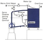
A typical arrangement is shown in Fig.2. The purpose of automatic temperature control is to prevent excessive cooling which could cause condensation within the cylinder, and to ensure that water is not wasted.
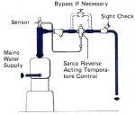
Fig. 2 Sarco Temperature Control Controlling Mains Water Cooling of Single-Stage Compressor
Table 5 Cooling Tank Capacity
|
Compressor
Capacity dm3/s free air |
Tank
Capacity litres |
| 10 | 170 |
| 25 | 370 |
| 50 | 700 |
| 70 | 1020 |
| 100 | 1600 |
| 140 | 2200 |
| 200 | 3000 |
| 280 | 3800 |
| 350 | 4500 |
The methods shown in Figs. 1, 2, 3, 6 and 8 have been commonly used satisfactorily for many years all over the world and in many cases mains water is used.
It should be noted however that some water supply authorities will not permit the water from their supply mains to be used in this way particularly where it is finally discharged to waste.
It is important that the control never stops the flow of cooling water completely. If this were to happen the water surrounding the sensor would become stagnant and might cool down to such an extent that the sensor would not open the valve again. Some Sarco Valves incorporate an adjustable bleed so that a small flow is maintained at all times. If there is no bleed valve a small bore by-pass controlled by a needle valve should be fitted.
Fig.3 shows a typical cooling water circuit for a two-stage machine fitted with intercooler. To get the best out of the intercooler it needs cold water to reduce the air temperature as much as possible. This will reduce the energy requirements of the compressor. It can also separate out some of the water in the air which was in vapour form at the higher temperature. The warmed water from the intercooler then goes to the first and second stage cylinders. Although compressor manufacturers optimum cooling water leaving temperatures from the cylinders vary, they tend to be in the 35-49C region. To ensure this requirement is met and to conserve cooling water when this comes from the mains, it is advisable to fit a temperature control as shown, with reference to the compressor manufacturer.
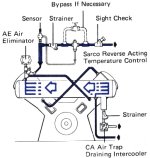
Fig. 3 Sarco Temperature Control Controlling Mains Water Cooling of Two-Stage Compressor
One thing which we must always consider when mains water is used for cooling is that the pressure may be high and will almost always fluctuate. Wide fluctuations in pressure may make temperature control difficult in which case it would be worth fitting a pressure reducing valve or a break tank to maintain a steady pressure of no more than about 15 bar. As a check that water is flowing, the outlet pipe from the compressor can be led to an open tundish or incorporate a water flow indicator - the Spirax Hills Sight Check is an inexpensive device which is ideal for this purpose.
As far as water saving is concerned, it is well worth noting the amount of water required for a compressor system. The water quantities given below are the minimum normally required, and are likely to be much higher unless an automatic temperature control is fitted.
| per 100dm at 7 bar | |
| Single Stage | 015 litre/s |
| Single Stage with After cooler | 065 litre/s |
| Two Stage | 035 litre/s |
| Two Stage with After cooler | 080 litre/s |
iv) Closed Cycle Cooling
So far, we have dealt with cooling of small compressors dissipating heat through a holding tank and with somewhat larger ones using mains water. As shown in Figs. 2 and 3, the use of an automatic temperature control will prevent over cooling problems and will keep water consumption to a minimum. However, the use of mains water is often considered wasteful especially during times of local water shortage. It is usually better, particularly with larger compressors, to operate them on a closed circuit, the heat being dissipated either through a cooling tower or through a mechanical cooler. Another advantage is that a closed circuit can eliminate jacket scaling, particularly if the water is treated.
The use of the closed circuit does not, of course, mean that temperature control is unimportant. With the closed circuit, it is usually preferable to use a Sarco Three Way Temperature Control as shown in Fig. 4. The Sarco Type 58 Valve is suitable where the demand is for 50 mm and over, and for sizes below this the Sarco TW Valve can be used.
One important thing to remember about cooling towers is that in severe winter conditions it is not uncommon for them to freeze solid. If this happens, of course, the compressor has to be shut down.
Freezing of the sump may be prevented by fitting a heating coil supplied with steam controlled by a Sarco Temperature Control as shown in Fig. 5. The control should be set to open only when the water temperature falls below 20C so that no steam is used when it is not required. To prevent the tower becoming a solid mass of ice, the line from the diversion control valve should be so valved that it can return the water from the compressor direct to the sump instead of to the top of the tower in such low temperature conditions.
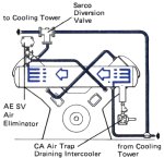
Fig. 4 Sarco Diversion Valve Controlling Compressor on Closed Circuit Cooling
Under these circumstances, sufficient cooling can usually be maintained due to heat losses from the sump itself.
A mechanical cooler, where the cascade of water is cooled by forced or induced air draught, is much smaller than the cooling tower and the elements are almost totally enclosed so there is less risk of freezing when shut down. However, any ice which does form will usually melt within seconds of the compressor starting up.
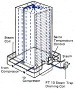
Fig. 5 Sarco Temperature Control Controlling Temperature of Cooling Tower Sump
v) Rotary Compressors
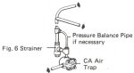
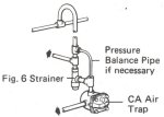
Where the compressor is of the rotary-vane type a further point needs consideration. Oil is usually injected into the compressor chamber to form a seal between the blades and the casing and to act as an internal coolant. This oil is removed from the air by a separator at the discharge and is then passed back to the sump by way of a water cooled heat exchanger.
This heat exchanger normally uses mains water, and a temperature control can be fitted as in Fig. 6 to give efficient temperature control and regulate water flow. Oil coolers may also be fitted to the main lubrication system of large reciprocating machines, again using the same cooling circuit layout shown in Fig. 6.
C) Cooling the Air
The whole purpose of the compressed air installation is to deliver air to the point of use in the best possible condition - clean, dry and with the minimum of loss of pressure. If we fail on any one of these counts, then there is likely to be increased wear on tools, poor performance, particularly in things such as paint spray equipment, and the operating costs will inevitably be higher than they ought to be.
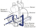
Fig. 6 Sarco Temperature Control Controlling Flow of Mains Water to Oil Cooler
Table 6 Moisture Content of Air (100% RH)
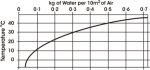
Let us consider moisture. Atmospheric air always contains a proportion of water vapour. How high this proportion is will depend on the relative humidity. In Britain, this may be somewhere between 50 and 75% - though it will be highest in foggy or rainy weather or if the inlet of the compressor is over a pond or stream or other damp area, a point by the way which is well worth watching when installing compressors.
But just how much water can be held by a given volume of air will depend upon its temperature.
The moisture carrying capacity of air increases with a rise in temperature and conversely, and perhaps of greater importance to us at this stage, it decreases with a fall in temperature. (See Table 6).
Its moisture carrying capacity also falls as the pressure is increased.
So when 'free air' containing water vapour under average conditions enters the compressor two things will happen. Its ability to hold the water will decrease as the air is compressed to a smaller volume but will increase because of the higher temperature resulting from the compression. Under average conditions the air will leave the compressor just able to carry its initial water content.
It will follow that any cooling which then takes place must cause the air to shed its excess water vapour by condensing and this can be accelerated by introducing artificial cooling devices such as intercoolers and aftercoolers.
Although it is customary to lag steam mains to retain heat, it is a potentially bad practice to lag the compressed air main between the compressor and the first major cooling plant (i.e. after cooler or receiver). If the pipework is lagged, the high discharge temperature of the compressed air may be sufficient to spontaneously ignite the deposits of oil, dirt, scale etc, commonly found in this first section of pipe. Once the air has cooled to near ambient temperature, this danger will not arise.
An intercooler is fitted between the stages of a multi-stage compressor; its purpose is to cool the air between the stages as shown in Fig. 3. But in cooling the air to reduce its volume it also serves the very useful purpose of condensing out the surplus water vapour which, if allowed to pass to the next compression stage, could condense on the cylinder walls with resultant damage to the compressor.
It is essential that the water is drained away from the intercooler and this can best be done automatically using one of the Spirax range of compressed air traps as described on pages 22 and 23. Fig. 7 shows a typical installation.
An after cooler should be fitted immediately following the compressor so as to remove as much water as possible before the air reaches the receiver.
The water must, of course, be drained from the bottom of the after cooler, and this is best done automatically. Manual drains will work but only if they are attended regularly. Rarely, if ever, is this possible, and an automatic drain trap arranged as in Fig. 8 is the best way of ensuring that the system operates properly.
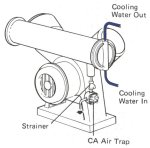
Fig. 7 Spirax Float Trap Draining Intercooler
The most efficient aftercoolers are usually water cooled and the lower the air temperature they can produce the better. However, there is a point of maximum efficiency so, for reasons of economy, where mains water is used, it is well worth fitting a Sarco Temperature Control to the water outlet, as Fig. 8, to keep consumption within reasonable bounds.
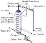
Fig. 8 Temperature Control Controlling After-cooler
For those areas where cooling Water S either not available or is too expensive, the air blast after cooler becomes the first choice. Ambient air is blown by an electric motor and fan over a bank of finned tubes, through which the compressed air flows. Although the compressed air discharge temperature is likely to be, on average, approximately 60C 100F higher than for a water cooled after cooler. the unit will still require automatic drainage by a trap, as shown in Fig. 9.
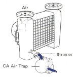
Fig. 9 Air Blast After cooler
Example (Metric SI Units)
How much moisture will separate out from air if the compressor inlet conditions are 200C and 70% relative humidity; the compressor delivers 1 m 3/s of free air compressed to 7 bar to the system at 25C?
Compressor takes in 1 m3/s.
From the graph (Table 6) water taken in will be
(0,18*70)/(10*100) = 0,0126 kg/s
Compression ratio at 7 bar 7.91 (Table 8).
Next we must find the volume of air after compression. Since its volume is proportional to the absolute temperature and to (1/compression ratio), 1m3 will occupy:
(1/7,91)*{(273+25)/(273+10)} = 0.128 m3
From the graph 10 m3 of air at 250C can carry 0.24 kg of water.
Therefore 0128 m3can carry:
0,128*(0,24/10) = 0,00307 kg/s
Therefore the amount of water which will separate out is:
00126 - 000307 = 000953 kg/s
D) Receivers
Important though aftercoolers are, it would be very unusual for all the water vapour in the air to condense at this point. Further cooling almost always takes place in the receiver as well as from the distribution system. The water vapour, (and oil mist, if the compressor is of the lubricated type) condenses in the receiver and collects at the bottom. On those installations where the compressor plant is small, an after cooler may not be fitted, thus making the receiver the point at which most condensed liquid will be found. If these liquids are allowed to build up, carryover into the mains system is likely. There is also the possible corrosion of the receiver itself.
It is, therefore, important to ensure that these collected liquids and solids (atmospheric dust, pipe scale, carbon, rust, etc) are automatically removed as they collect. Fig. 10 shows a typical vertical receiver: 1 and 2 show alternative positions normally found for the discharge pipe. As the trap and its protective strainer will have to handle varying proportions of water, oil, emulsion, dirt, etc, regular cleaning is essential. If excessive amounts of oil are being carried over from the compressor (generally indicating that maintenance of the compressor is required), the system shown in Fig. 11 may be found effective. A manual drain cock is fitted to the receiver a short distance up from the drain trap outlet. Oil and scum floating on the water surface (which might foul up the trap) can be periodically drained off.

Fig. 10 Typical Vertical Receiver
Apart from the receiver's ability to cool the air and hence deposit liquid (that is why it is better to site the receiver where the ambient temperature is low), it performs two other functions. For some applications, it is important that the pressure pulses produced by a reciprocating compressor be eliminated as far as possible. The receiver, therefore, acts as a pulsation damper. The receiver also acts as a power storage vessel, allowing intermittent high demands for compressed air to be met from a smaller compressor set.
Being a pressure vessel and thus subject to regular inspection, a receiver is fitted with inspection covers or man-holes. These also allow any solid contaminant build-up to be removed. To comply with the factory and safety acts a receiver must be fitted with an adequately sized safety valve and generally a pressure gauge is also fitted.
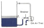
Fig. 11 Spirax Air Trap Draining a Receiver when Excessive Oil and Scum are Present

Fig. 12 Small Horizontal Receiver (Alternative Trapping Arrangements)
On small horizontal receivers, (see Fig. 12) generally supplied with the smaller industrial or garage type compressor, automatic drainage may be more difficult. The drain point is often in the centre of the dished end of the receiver or on the top. In each case, an internal dip pipe is fitted to allow the air pressure to displace the collected liquid when the manual drain is opened. An automatic trap, such as the Spirax Airodyn or Spirax Drayton IB Trap, can be used on these applications (the IB requires an initial water prime).
It is also worth while considering the capacity of the receiver. This is usually sized on the actual output in 1 minute from the compressor but where consumption is high and fairly constant the air is in the receiver for too short a time to cool down very much. Where this is so, the storage capacity is obviously low and it is better to size the receiver on plant consumption rather than on compressor output.
One compressor manufacturer recommends the following as a guide to receiver size:-
Receiver Capacity in m3 = m3 of free air required / Allowable pressure drop (bar)
For example:
A machine requires 3 m3 - available pressure is 7 bar and the minimum suitable pressure is 5,5 bar. So by using the formula to determine the receiver capacity
3/1,5 = 2 m3
2. The Distribution System
A) Layout
Although in an ideal system all cooling and condensing should be carried out before the air leaves the receiver, this is not very often achieved in practice. It is in fact impossible where after-coolers are not fitted. The whole of the compressed air mains therefore become additional cooling surfaces, the amount of condensing which takes place depending on the efficiency of moisture extraction before the air leaves the receiver and the temperature in the mains system itself.
Is is useless to provide a compressed air gun to blow out particles of swarf after a machining operation if, every time the operator used the gun, he squirts water all over the finished job. Equally, it can be very expensive to pass this water through compressed air operated tools. Care must therefore be taken in the layout of the mains so that adequate fall is given to proper drainage points.
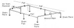
The general layout of the building will dictate the best positions for drain points but in general the main should be given a fall of not less than 1 m in 100 m in the direction of air flow and the distance between draining points should not exceed 30 m.
It is a good idea to form a distribution system as a ring main to help reduce pressure losses. It also makes the alteration or extension of the existing system easier. Drainage points should be provided by using equal tees and it assists in the separation of the water if these are arranged to change the direction of flow as shown in Fig. 13.
 |
|
|
|
|
|
Fig. 13 Spirax Air Trap Draining a Relay Point |
Fig. 13a Spirax Air Trap Draining a Branch Main |
Whenever a branch line is taken off the main, it should leave the top of it, so that any water in the main doesn't fall straight into the plant, and the bottom of the falling pipe should be drained as in Fig. 13a.
B) Separators
Whilst automatic drain traps will effectively deal with water which has collected at the bottom of the main or in a receiver of some kind, they can do nothing for the mist of water droplets which may be suspended in the air.
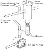
Fig. 14 Spirax Separator on Air Main
For most everyday applications much of this water can be removed by fitting a separator in the distribution mains, as Fig. 14. When a separator is fitted in a ring main system, install it so far as direction is concerned, to cater for the normal flow direction.
Spirax separators are available for this purpose in sizes 15 mm to 200 mm, the sizes 15 mm to 25 mm being of the type shown in Fig. 14 and are made of malleable iron suitable for a maximum pressure of 14 bar. The larger separators, i.e. 40 mm to 200 mm are of the type shown in Fig. 15 and are constructed of cast iron suitable for a maximum working pressure of 10 bar.
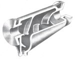
Fig. 15 Spirax Separator Sizes 1,5" to 8"
i) Dryers
There are applications where the air must be not only clean, but have a reduced dew point. This will call for more sophisticated and expensive methods to lower the dew point of the compressed air. Fig. l6shows the three common systems used for this purpose.
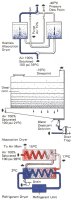
Fig. 16 Dryers
- Absorption Dryers These consist of two pressure vessels filled with a water adsorbing chemical. Wet compressed air is passed through one chamber until the chemical is saturated. Whilst this first chamber is being regenerated by heat and/or a purge of the ultra dry air, the second chamber is adsorbing moisture. An automatic control system alternates the chambers: one operational - one regeneration.
- Absorption Dryers These consist of a container of chemical, through which the compressed air passes. The chemical absorbs the water vapour, forming a solution which drains to the bottom of the container. This solution has to be discharged periodically by a drain trap, and the level of the desiccant then requires topping up. A domestic salt cellar is typical of this type.
- Refrigerant or Chiller Dryers These units are heat exchangers which will cool the air down to a theoretical dew point of 1 to 30C 34 to 370F and thus precipitate out the moisture. The system is a straight mechanical refrigeration unit with one extra facility included. This is a second heat exchanger whereby the outgoing cold, dry air is used to pre-cool the incoming compressed air supply. In doing so, the outgoing cold air is warmed up to somewhere about ambient temperature.
All these units incur running costs of some sort, whether it be compressed air for purging, steam or electrical power to reactivate chemicals, or the replacement of desiccant.
ii) Main Pressure Reduction
If is often necessary to reduce the mains pressure when supplying groups of plant or complete workshops. This requires a pressure reducing valve having quite a large capacity and very good flow characteristics. This unit is somewhat different in type from the small regulators used for individual pieces of plant which are described on page 25.
The Spirax DP Reducing Valve is shown in Fig. 17. It is of the diaphragm operated pilot controlled type and will give very close control of downstream pressure, but should not be used on compressed air where dead end service is required.
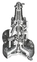
Fig. 17 Spirax DP Reducing Valve
As a steam reducing valve the Spirax DP has been very successful operating on dead end conditions its single seat stainless steel valve being particularly suitable for steam operation, and any mere wisp which does happen to pass the seat will be condensed by radiation loss in the downstream pipework before any pressure can build up.
But with the dryer conditions of compressed air, metal to metal seat closure is not so positive and, of course, any leak cannot be absorbed by condensing.
Fig. 18 shows the installation of a Spirax DPR Reducing Valve. The downstream pressure of the DPR is adjusted remotely by varying the pilot control signal supplied from the small pressure regulator. Table 7 gives details, sizes and capacities of the DP and DPR Reducing Valves.
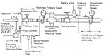
Fig. 18 Installing the Spirax DPR Reducing Valve

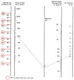
Table 7 Metric SI Units DP/DPR Reducing Valve Sizing and Capacities
How to use the chart
Capacities are given in cubic decimeters of free air per second (dm3/s). The use of the capacity chart can be best explained by an example.
Required, a valve to pass 55 dm3/s of free air reducing from 8 bar to 5 bar. Find the point at which the curved 8 bar upstream pressure line crosses the horizontal 5 bar downstream pressure line. A perpendicular dropped from this point shows that whereas a 1/2" LC valve will only pass 22,5 dm3/s and is therefore not large enough, a 1/2" valve will pass about 67 dm3/s under these conditions and is the correct valve.
C) Sizing Compressed Air Mains
The compressed air mains are the all-important link between the compressor and the point of usage.
It is thoroughly bad to install mains which are too small and cause high pressure drop. If, for example, a compressor has to work at 8 bar, to cater for pressure drop conditions, whereas 7 bar would normally meet the case, it calls for an additional power input of as much as 10%.
Mains which are too small also cause high velocity, making it difficult to separate the water from the air because much of the condensed vapour running as a stream of water along the bottom of the pipe, will be whipped up by and carried along with the fast moving air stream.
Whilst a watchful eye must be kept on the pressure drop, it is common practice to size compressed air mains on velocity and a reasonable figure for all practical problems is 6-9 m/s which is sufficiently low to prevent excessive pressure drop on most systems and will allow moisture to precipitate out without re-entrainment.
Many compressed air systems are working inefficiently because the demand has outgrown the supply - new pneumatic plant has been added from time to time without addition to the compressor plant or mains.
In designing a new plant, therefore, some thought might be given to possible future demands and allowance made in the mains sizes.
Sizing by velocity presents an easy form of determining pipe size for a given duty, but it must be remembered that the duty of a compressor and the demand of the equipment is usually expressed in dm3/s of free air and that when compressed, the volume will be less.
Table 8 shows that ratio of compression and the actual volume occupied at any given pressure can be found by dividing the volume of free air by the ratio of compression.
Table 8 Metric SI Units Ratio of Compression
| Gauge Pressure bar | 05 | 1 | 2 | 3 | 4 | 5 | 6 | 7 | 8 | 10 | 12 | 14 | 18 |
| Ratio of Com ression | 15 | 199 | 297 | 396 | 495 | 594 | 692 | 791 | 89 | 1087 | 1285 | 1482 | 1877 |
Example (Metric SI Units)
At a gauge pressure of 8 bar, Table 8 shows the ratio of compression as 89 so if we have 190 dm3 of free air compressed to 8 bar, it will occupy a space of:
190/8,9 = 21,35 dm3
Table 9 shows the equivalent volume already worked out for some of the more everyday pressures.
|
Volume of Free Air |
Equivalent Volume (dm3) when compressed to gauge pressures of |
||
|
dm3 |
4bar |
5bar |
7bar |
|
5 |
101 |
084 |
063 |
|
10 |
202 |
168 |
126 |
|
15 |
303 |
252 |
190 |
|
20 |
404 |
337 |
253 |
|
25 |
505 |
421 |
316 |
|
30 |
606 |
505 |
379 |
|
35 |
707 |
589 |
442 |
|
40 |
808 |
673 |
506 |
|
50 |
101 |
842 |
632 |
|
60 |
121 |
101 |
758 |
|
70 |
141 |
118 |
885 |
|
80 |
162 |
135 |
101 |
|
90 |
182 |
151 |
114 |
|
100 |
202 |
168 |
126 |
|
125 |
252 |
210 |
158 |
|
150 |
303 |
252 |
190 |
|
175 |
353 |
295 |
221 |
|
200 |
404 |
337 |
253 |
|
225 |
454 |
379 |
284 |
|
250 |
505 |
421 |
316 |
|
275 |
555 |
463 |
348 |
|
300 |
606 |
505 |
379 |
|
350 |
707 |
589 |
442 |
|
400 |
808 |
673 |
506 |
|
500 |
1010 |
842 |
632 |
|
750 |
1510 |
1260 |
960 |
|
1000 |
2020 |
1680 |
1260 |
|
1250 |
2520 |
2100 |
1580 |
Table 10 shows the volume of air which can be carried by various sizes of pipes at given velocities.
Velocity |
Volume of air through medium grade steel pipe, to BS 1387, minimum bore (mm) |
|||||||||||
m/s |
15 |
20 |
25 |
32 |
40 |
50 |
65 |
80 |
100 |
125 |
150 |
200 |
30 |
06 |
11 |
17 |
30 |
41 |
65 |
109 |
151 |
257 |
392 |
562 |
985 |
35 |
07 |
13 |
20 |
35 |
47 |
76 |
127 |
176 |
300 |
457 |
665 |
1150 |
40 |
08 |
14 |
23 |
40 |
54 |
87 |
146 |
201 |
342 |
522 |
749 |
1310 |
45 |
09 |
16 |
26 |
45 |
61 |
98 |
164 |
226 |
385 |
588 |
842 |
1470 |
50 |
10 |
18 |
28 |
50 |
68 |
108 |
182 |
251 |
428 |
654 |
936 |
1640 |
55 |
11 |
20 |
31 |
55 |
74 |
119 |
200 |
276 |
471 |
719 |
1030 |
1810 |
60 |
12 |
21 |
34 |
60 |
81 |
130 |
218 |
301 |
513 |
785 |
1120 |
1970 |
65 |
13 |
23 |
37 |
65 |
88 |
141 |
237 |
326 |
556 |
850 |
1220 |
2130 |
70 |
14 |
25 |
40 |
70 |
95 |
151 |
255 |
351 |
599 |
915 |
1310 |
2300 |
75 |
15 |
27 |
43 |
75 |
101 |
162 |
273 |
376 |
642 |
980 |
1400 |
2460 |
80 |
16 |
28 |
45 |
8 |
108 |
173 |
291 |
401 |
685 |
1050 |
1500 |
2630 |
85 |
17 |
30 |
48 |
85 |
115 |
184 |
310 |
426 |
728 |
1110 |
1590 |
2780 |
90 |
18 |
32 |
51 |
90 |
122 |
195 |
328 |
451 |
771 |
1180 |
1690 |
2960 |
Pipe sizing is, therefore, reduced to simplicity by using these tables.
Example (Metric SI Units)
To determine the size of a main to carry 100 dm3/s of free air at a working pressure of 7,0 bar.
From Table 8 it will be seen that at 7,0 bar the ratio of compression is 7,91 so the actual volume of 100 dm3 of free air when compressed to 7,0 bar is:
100/7,91 = 12,64
Alternatively, because 7,0 bar is a pressure in everyday use, Table 9 will give the answer direct without the bother of working it out.
Having decided that the velocity shall not exceed 6 m/s, from Table 10 we can determine the size of pipe required to carry 12,64 dm3/s of air.
Casting an eye along the line opposite 6 m/s in the left hand column (Table 10) we find that a 50 mm pipe will carry 13,00 dm3/s and is the nearest commercial size to our requirements.
For long runs the pressure loss through mains sized by the velocity method may be higher than desirable and it is as well to check what the actual pressure drop will be.
It is of course only possible to obtain rough estimates as so much depends on the type and condition of the pipe and on the resistance of the various fittings.
In calculations it is usual to allow far fittings by considering them in terms of straight length of pipe and Table 11 shows the equivalent lengths in metres feet for typical fittings.
Table 11 Metric SI Units Resistance of Pipe Fittings (Equivalent Length in m)
Type of Fitting Nominal Pipe Size (mm) 15 20 25 32 40 50 65 80 100 125 Elbow 026 037 049 067 076 107 137 183 244 32 90° Bend (long) 015 018 024 038 046 061 076 091 12 152 Return Bend 046 061 076 007 12 168 198 26 366 488 Globe Valve 076 107 137 198 244 336 396 518 732 945 Gate Valve 0107 014 018 027 032 040 049 064 091 120 Run of Standard Tee 012 018 024 038 040 052 067 085 12 152 Through Side Outlet of Tee 052 070 091 137 158 214 274 366 488 640 By adding the equivalent lengths to the actual length of pipe, the loss in each section of a system can be easily found by reference to the chart.
The nomogram in Table 12 gives a ready means for determining pressure drops through pipes often found in industry (this information for smaller bore pipes is set out in Table 15). It is based on the following formula which can also be used for pipe sizes outside those shown in the table.
Pressure drop in bar = (KLQ2)/(R*d5,3)
Where
K = 800
L = Length of pipe in metres
Q = The volume of free air in dm3/s passing through the pipe.
R = The ratio of compression at the beginning of the pipe
d = The internal pipe diameter in mm
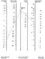
Table 12 Metric SI Units Pressure Drop in Steel Pipes (16 mm to 100 mm)
Example (Metric SI Units)
To determine size of pipe needed to pass 300 dm3/s free air with a pressure drop of not more than 300 mbar in 125 in of pipe. Air pressure is 9 bar.
300 mbar in 125 is equivalent to 300/125 = 2,4 mbar/m
Join 9 bar on the air pressure line to 24 mbar/m on the pressure drop line and project to cut reference line at X. Join X to 300 dm3/s and project to cut pipe size line at approximately 61 mm.
Therefore choose pipe having a minimum bore of at least 61 mm (a 65 mm nominal bore pipe to BS 1387 has a bore of 69 mm and would therefore meet the case and give some margin).
3. Compressed Air Drain Traps
We have emphasized how important it is that an automatic device be used to drain water from different parts of the compressed air installation.
Generally, the ball float type of drain trap is the most common because it gives a positive shut off opening only to the presence of water and closing immediately the water has been cleared.
Take for example the Spirax CA 550 Air Trap as shown in Fig. 19 which can be used at pressures up to 14 bar. It has " or 3/4" connections, a synthetic rubber valve to ensure a dead shut off, and a malleable iron body.
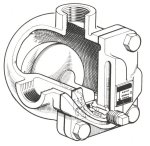
Fig. 19 Spirax CA 550 Compressed Air Trap
Water coming into the trap will cause the float to rise opening the main valve, and as the water is discharged so the float will follow the lowering level until the main valve is once again closed.
So long as large quantities of water are coming to the trap it will be seen to be discharging. But often because the trap is draining the plant continuously, so little water is handled at any one time, there is no visible discharge. The fact is that a mere teaspoonful of water discharged with high air pressure behind it, leaves the trap orifice as no more than a mist, so don't be misled into thinking that the trap is not working properly just because there is no obvious discharge.
A mechanical trap such as the CA 550 must open to water yet close off to air and so cannot incorporate any automatic device to prevent air binding as can a steam trap.
When connected to any compressed air plant, if there is the possibility of large quantities of water coming to the trap, then air binding can take place.
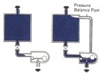
Fig. 20 & Fig. 21
This can be explained as follows:
Let the pot A, Fig. 20 be a drain point- it can be part of the pipeline or a receiver or any low point into which the water collects, and is under pressure.
It contains some water in the base and to get rid of this a trap is fitted B.
Now because the trap valve is in the closed position, when the valve C is opened water will occupy the whole cross sectional area of the pipe will start to pass down towards the trap gradually compressing the air in the trap body.
But when the pressure in the trap body is equal to the pressure in the drain pot nothing will induce the water flow into the trap.
So, although there is water there, it cannot get to the trap due to air binding.
This can happen without manipulation of the valve C if, during normal running or starting conditions, a large quantity of water can suddenly arrive at the drain point.
But it can be overcome by fitting a balance pipe as in Fig. 21.
With this arrangement the water will flow freely into the trap displacing air which passes through the balance pipe and into the main system.
Where the amount of water coining to the trap is small it may be said that this balance pipe is unnecessary because the water will travel down the sides of the pipe, allowing air to be displaced through the centre of the pipe.
Practical experience will determine whether this is so, but if in any doubt it is always safest to fit the balance pipe to make sure that the water can get to the trap.
Although the CA 550 Trap will handle water lightly contaminated with oil, all types of trap are susceptible to this particular form of contaminant. With the build up of emulsion, the trap may become sluggish or cease to operate at all. Regular maintenance is necessary to maintain performance. The Spirax Dri-Line Air Trap is a pilot operated, blast discharge unit and is shown in Fig. 22. Whereas a ball float trap produces a Constant discharge, the Dri-Line only blasts open when a specific quantity of liquid has been collected.
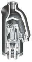
Fig. 22 Spirax Dri-Line Air Trap
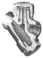
Fig. 23 Spirax Airodyn
The Spirax Airodyn (Fig. 23) may be looked upon as a special purpose drain trap.
Firstly where the air pressure is above the normal limit of the float trap, the Airodyn is suitable for use up to 24 bar.
Its second purpose is to handle water more heavily contaminated than usual with oil which it will do at pressures ranging from 1-4 bar 20 psi to 24bar. This can be particularly useful where the amount of oil is excessive due perhaps to a badly worn compressor. True that the right answer to such an operating condition is that the compressor needs an overhaul, but this is not always practical.
This is where the Spirax Airodyn. which has been designed so that it can be modified on site to accommodate varying degrees of Contamination, can in many cases be useful, although we must point out that there is a limit to how much oil the trap can handle and if the presence of so much oil to due to a much worn compressor, it may well be costing more than an overhaul in loss of efficiency. For those occasions where higher pressures are involved (up to 62 bar) it may be possible to use the Spirax Drayton Inverted Bucket Trap as shown in Fig. 24. This has a forged steel body with flanged connections.
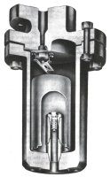
Fig. 24 Spirax Drayton Inverted Bucket Trap
But when choosing this, or any other blast discharge trap such as the Airodyn, it is extremely important to keep an eye on the capacity of the compressor and to avoid at all costs over-sizing the trap, or using these types on compressors of very low output.
4. Using the Air
Having laid out the air mains and branch lines we come to the points of use. Compressed air is used for many purposes. Typical examples are high speed air motors, operating tools such as drills and wrenches; linear actuators and directional control valves working many types of machine tools and process equipment; air guns or dusters giving an air blast for cleaning purposes, paint spray equipment, pneumatic control equipment, air gauging and many others.
A) Filters
All atmospheric air carries both dust and moisture; some of this moisture condenses out after compression. Table 6, page 8, gives an idea of what can be expected for any set of conditions. Although some water, oil and dirt will have been removed by the separators and traps in the mains, there will always be some which will be carried over. Moreover, pipe systems accumulate scale and other foreign matter, such as small pieces of gasketing material, jointing compounds, and so on. Burnt compressor oil can also be carried over in Pipework, and this, with other contaminants, forms a gummy substance. To remove these, all of which are liable to have deleterious effects on pneumatic equipment, the air should be filtered as near as possible to the point of use. Spirax-Monnier Filters have been designed for this type of application.
Some engineers wonder how best to choose a filter for a specific application. Most filters are designed to remove some of the larger particles of foreign matter, including liquid droplets, by means of centrifugal action -whirling the heavier particles against the outside of the filter bowl from which they drop into the sump. This reduces the amount of dirt that the filter element or cartridge has to handle, and in consequence increases its working life. In most cases they are designed to handle air flows normally associated with Pipework which they have been made to fit.
Filter elements can be broadly divided into two categories, and the first of these is a surface type element i.e. one which has a uniform pore size of material throughout its depth, and whose useful service life is a function of the free surface area of the element. Perforated or mesh screens and sintered metal fall into this category. The second type of element uses a graded density cartridge, i.e. one in which the pore size decreases in the direction of flow. This type of element has, therefore, "volume capacity" to hold dirt. In addition to the dirt which collects on the outer surface of the element, it will also hold substantial quantities in the core of the cartridge, and this increases its useful life.
Filter elements are normally rated in microns, and this rating gives an indication of the finest particle that will be stopped by a clean element. It is inadvisable to use a finer element than is necessary, because this will obviously decrease its working life.
Spirax-Monnier Filters have a see-through bowl, and are shown in Fig. 25. Although the bowl material is extremely strong it can be degraded by various chemical substances in particular solvents. For safety therefore bowl guards can be supplied with the units to prevent injury to personnel should a bowl fail. Metal bowls are also available.
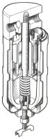
Fig. 25 Spirax-Monnier Compressed Air Filter
When a very high degree of filtration is required as for example, in many fluidic applications where the air should be oil-free, for air gauging equipment etc, a high efficiency coalescing filter may be required. A Spirax-Monnier unit of this type is shown in Fig. 26. This type of filter has two separate functions. With the air flow through the filter element being from inside to outside, the element first of all removes the very fine particles of solid contaminate by direct filtration. Finely dispersed aerosols of oil and water in the air gradually migrate through the filter element and in doing so, they "coalesce" or grow in size.
To assist in this growth and to eliminate re-entrainment, a further layer of material is provided through which the air has to pass. The larger drop of oil/water thus formed can then be easily separated from the air stream by gravitational forces. The collected liquid, of oil and water, will then fall into the bottom of the filter bowl from which it can be drained, manually or automatically.
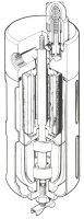
Fig. 26 Spirax-Monnier Coalescing Filter
It is important, however, with this type of high efficiency filter (although it applies to standard filters as well) to keep within the recommended flow conditions. To lengthen the life of a coalescing filter, it is a good idea to precede it with a standard filter with either manual drain as shown in Fig. 25, or with an auto-drain as shown in Fig. 27.
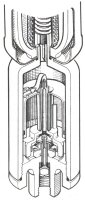
Fig. 27 Spirax-Monnier Auto-Drain
We listed in the first paragraph under the heading of Filters, various sorts of contaminants these would remove. The one which comes over in greatest bulk by far in most compressed air systems is water, and this usually also contains dirt and burnt compressor oil, and often forms a slightly viscous emulsion. It will collect in the sump of the filter and must be drained off because if its level is allowed to build up, then it will be forced through the filter element into the very system it is designed to protect. Draining can be done automatically by a Spirax-Monnier Auto-Drain, as shown in Fig. 27. This is by far the best because you do not then have to rely on an operator to carry out this duty at regular intervals.
Not only can Auto-Drains be supplied already fitted to the standard series of Spirax-Monnier Filters, but they can also be fitted to existing filters in the field. In these cases a conversion kit of the necessary parts is available. The Auto-Drain is extremely efficient and a useful addition, particularly on automatic plant.
B) Regulators
Many pneumatic operations must be carried out at a lower pressure than that of the main supply. Examples are air for instruments and controls and for clamping components while work is done on them. We have already mentioned the waste that occurs when power air is used at an unnecessarily high pressure. If air can be used at 4 bar instead of 5-5 bar, this will result in a saving of about 20% of the free air used. Remember, however, that insufficient pressure or air flow may reduce efficiencies of, for example, an air powered tool.
A further reason for reducing air pressure is safety. If air guns or dusters used for cleaning purposes are run at too high a pressure, dirt and swarf can be blown about with considerable force, sometimes with dire consequences. So pressure regulators are required to reduce the pressure to the correct value and also to ensure that it remains reasonably constant at the point of use.
Regulators basically fall into two categories. One class is the pilot-operated type, like the Spirax DP Reducing Valve, described on page 13 which will give very close control of downstream pressure, irrespective of throughput. The second type is the simpler, direct-acting regulator, which will give a small variation of downstream pressure as the flow rate varies. These direct-acting regulators are perfectly satisfactory for the vast majority of pneumatic applications. The Spirax-Monnier Regulator is of this type and is illustrated in Fig. 28.
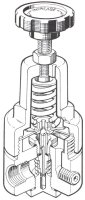
Fig. 28 Spirax-Monnier Regulator
It is of the self-relieving type, and incorporates a small relief valve which allows excess air to bleed away, should the downstream pressure exceed the set value, It also has the advantage of allowing the control pressure to be reduced without the necessity of breaking pipe connections to bleed off some of the air. It should be used whenever the control pressure has to be varied periodically.
C) Lubricators
Where air is used to drive air motors, cylinders and valves, a lubricator should also be fitted. Lubricated components - since friction is reduced by the oil film - can work at lower air pressures, and what is more important, require less maintenance. Essentially a lubricator is a reservoir of oil which has been designed so that when air is flowing, a metered amount of oil is fed, in mist form, into the air stream. This oil will be carried with the power air to the point of use to lubricate all moving parts.
All lubricators require a certain minimum rate of air flow to induce oil into the air stream; their design should be such that once the air flow exceeds this minimum rate they will give satisfactory lubrication for higher rates of flow, without causing an excessive pressure drop. Moreover, they should be easy to set up, able to work on intermittent air flows, and to maintain a constant oil to air ratio, irrespective of air flow rate, without readjustment, It is an advantage if it is easy to see whether the lubricator is working or not, by visually checking the oil drip rate.
The Spirax-Monnier Lubricator meets all these requirements, and is shown in Fig. 29.

Fig. 29 Spirax-Monnier Lubricator
The best person to advise on the type of oil to be used in these pneumatic applications is, of course, the supplier of the tool or component that is to be lubricated. Where no guide is given, we would recommend a light free-fogging lubricating oil with a high velocity index. Oils with lead additives should be avoided, as oil vapour will be discharged from the exhaust valves of the pneumatic equipment, and lead is toxic. If the oil being used or the environment contains substances not compatible with polycarbonate it may be necessary to use a lubricator with a metal bowl. The ratio of oil to air can best be decided experimentally, although as a rough guide at 5,5 bar one drop of oil per minute for every 5 dm3/s of free air is regarded as satisfactory.
We are sometimes asked where is the best place to fit filters, regulators and lubricators. The answer is to fit them as close as possible to the equipment being served. Where lubricators are used to provide oil for linear actuators or for any application where the direction of air flow is reversed, a good rule to follow is that the volume of the pipework between the lubricator and the cylinder should not exceed about 50% of the volume of free air used by the cylinder per stroke.
Example (Metric SI Units)
If we have to lubricate a cylinder 40 mm diameter by 50 mm stroke, working at a gauge pressure of 4 bar, what is the maximum length of 8 mm copper tube that should be used between the lubricator and the cylinder?
The free air used per stroke = {(pi/4)*(40)2 *50}*{(4+1,013)/1,013} = 310930 mm3
50% of this figure = 155465 mm3
The minimum internal diameter of 8 mm 20 swg copper tube (see Table 13) is 6,32 mm.
So the volume per metre run = (pi/4)*(6,32)2 *1000 = 31 370 mm3
Therefore, the lubricator should not be more than :- (155465/31370) = 5m from cylinder
In practice, it is advisable not to exceed 7,5 - 9m
For uni-directional flow (say to an air tool) this distance can be exceeded.
Table 13 Metric SI Units Some Standard Tube Dimensions
| Steel Tubes to BS 1387 |
Copper Tubes to BS 2871 Pt 2 Table 4 Medium |
Preferred Sizes of Nylon Tube CETOP RP54P - up to 30C Light Gauge |
||||||
| Nominal Bore | Med Weight Min ID | Heavy Weight Min ID | OD | Thickness | Min ID | OD | Min ID | Max Working Pressure |
| mm | mm | mm | mm | mm | mm | mm | mm | bar at 30C |
| 6 | 58 | 45 | 3 | 06 | 172 | 4 | 277 | 12 |
| 8 | 86 | 75 | 4 | 06 | 272 | 5 | 355 | 13 |
| 10 | 121 | 110 | 6 | 08 | 432 | 6 | 424 | 13 |
| 15 | 158 | 146 | 8 | 08 | 632 | 8 | 574 | 14 |
| 20 | 213 | 201 | 10 | 08 | 832 | 10 | 724 | 14 |
| 25 | 269 | 253 | 12 | 10 | 990 | 12 | 924 | 11 |
| 32 | 356 | 340 | 16 | 10 | 139 | 16 | 1274 | 10 |
| 40 | 415 | 399 | 18 | 147 | 9 | |||
| 50 | 525 | 508 | 22 | 181 | 9 | |||
| 65 | 681 | 664 | 28 | 2314 | 9 | |||
| 80 | 800 | 784 | ||||||
| 100 | 1040 | 1020 | ||||||
| 125 | 1290 | 1280 | ||||||
| 150 | 1540 | 1530 | ||||||
Note: 1 bar = 100 kPa
D) Interconnecting Pipework
There is also the question of piping up the cylinders, valves, air tools and other equipment. It is normal practice to allow much higher pipe velocities in the circuit piping than in the compressed air main network. The reason for this is that pipe runs are normally short, and the higher velocities do not therefore cause unreasonably high pressure drops., More over, it has the advantage that it keeps the layout neat and compact. At 5,5-7,0 bar 18 to 24 m/s is quite a normal pipe velocity for this interconnecting pipework. At low pressures, however, it is advisable to keep the velocity down.
Table 14 gives details of the relationship between pipe diameter, air pressure, flow rate and velocity. Table 15 allows a check to be made that the pressure drop resulting from this velocity is acceptable. It is important to note when using these tables, that the pipe diameter referred to is actual bore size, and not nominal pipe size. The reason for this is that pressure drop is a function of (diameter)5, and a small difference in diameter can therefore have a marked effect on pressure drop. Table 13 gives the actual pipe bores of various types of pipe and tube.
Table 14 Metric SI Units Pipe Carrying Capacities at Varying Velocities
To select a suitable pipe size it is necessary to know how much air it will have to pass. Most manufacturers of pneumatic equipment quote figures of free air consumption. Table 16 gives a list of average rates of air consumption of different types of equipment taken from manufacturers' catalogues, and can be used as a rough guide if actual figures are not available.
When evaluating how much air a cylinder uses, it is important to remember that it is the rate of air flow which should be the determining factor.
Example (Metric SI Units)
If a single-acting cylinder 50 mm bore x 150mm stroke, working pressure 4 bar strokes three times in one minute with each stroke taking 0,75 s, the rate of consumption whilst the cylinder is stroking
= (pi/4)*{(0,52*1,5)/0,75}*{(4+1,013)/1,013} = 19 dm3/s
Had it been a double acting cylinder (assuming the same time to minus stroke and disregarding the effect of the piston rod), the rate of consumption would be the same, although the air used per minute would be 87 dm3.
Example (SI Metric Units)
Using the example in Table 14 to determine the velocity of the air. Join 7 bar to 3,1 dm3/s and project to cut reference line at Y. Join Y to pipe diameter line for 12mm nylon tube. Read off where this cuts air velocity line which is a little over 6 m/s.
Table 15 Metric SI Units Pressure Drop in Pipes and Tubes (25 mm to 15 mm)
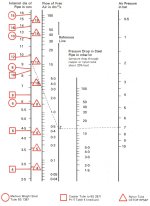
Example (Metric SI Units)
How much air at 7 bar can you pass through a nominal 12 mm CD tube (BS 2871) so that the pressure drop does not exceed 10 mbar/m.
Because the pressure drop through nylon tube is 20% less than through steel the equivalent pressure drop through steel pipe (as shown on nomogram) would be 125 mbar/m.
Join 7 bar on air pressure line to 125 mbar/m on pressure drop line and produce to meet reference line at Z. Join Z to pipe size for 12 mm CD tube. The latter cuts air flow line at 31 dm 3/s. The maximum amount of air you can put through the tube if the pressure drop must not be exceeded is 31 dm 3/s.
Table 16 Metric SI Units Typical Air Consumption of Pneumatic Tools and Appliances at 5,5 bar
| dm3/s of free air at 55 bar | |||
| Drills | 7mm | 47 - 75 | |
| 10mm | 71 - 94 | ||
| 13mm | 118 - 141 | ||
| 25mm | 283 - 377 | ||
| 50mm | 377 - 566 | ||
| 75mm | 472 - 614 | ||
| Grinders for mounted points | 47 - 118 | ||
| For arbor mounted wheels |
50 mm dia |
94 - 118 | |
|
Grinders up to 150mm dia |
236 - 283 | ||
| Sanders and Polishers | 47 - 211 | ||
| Torque Wrench for nuts up to | 7mm | 47 - 71 | |
| 13mm | 118 - 165 | ||
| 25mm | 189 - 260 | ||
| 38mm | 236 - 330 | ||
| Screwdrivers | 33 - 118 | ||
| Nut Runners | 47 - 141 | ||
| Spray Guns (at 34 bar) | Small | 047 - 24 | |
| Medium | 24 - 57 | ||
| Large | 57 - 118 | ||
| Blow Guns | 24 | ||
| Air Motors | up to 1 BHP (746W) | 141 - 165 per BHP (746W) | |
| 1 to 5 BHP (746-3730W) | 141 per BHP (746W) | ||
| over 5 BHP (3730W) | 118 perBHP(746W) | ||
Picture Under Construction
Fig. 31 Typical Installation
A Typical Application
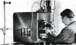
Air Operated Welding Machine
Correctly conditioned compressed air ensures reliable operation at minimum cost.
5. Further Details
Remember, that to get the best results from your compressed air installation, you must make sure that, you have a sufficient volume of air at the point of use, at the correct pressure, clean, dry and if necessary lubricated, at the minimum cost.
We have highlighted some of the points you should bear in mind but would be pleased to offer more detailed advice if you will contact us. Alternatively. may we suggest that you ask our Regional Engineer to call. We would like to add, we make no charge and you are under no obligation if you wish to take advantage of our offer.
A number of Spirax Sarco products have been mentioned in this Information Book and further details are available as follows:-
Sarco Temperature Controls
Spirax Hills Sight Check
Sarco TW Valve
Spirax CA 550 Compressed Air Trap
Spirax CA 105 Compressed Air Trap
Spirax Airodyn
Spirax Drayton Inverted Bucket Trap
Spirax Separators
Spirax DP Reducing Valve
Spirax DPR Reducing Valve
Spirax Dri-Line
Spirax Monnier Filters
Spirax Monnier Lubricators
Spirax Monnier Oil Removing Coalescing Filter
Spirax Monnier Regulator
Spirax Monnier Auto-Drain
Spirax Safety Valve
Spirax Strainer
Spirax Pressure Gauge
![]()