 |
 |
 |
 |
 |
 |
Voith Turbo Couplings with constant filling
Voith Turbo Couplings - proven a million times
As an expert for difficult tasks in power transmission Voith meets the steadily increasing requirements in practice and convinces through innovative performance.
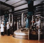
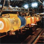
Constant-fill Voith Turbo Couplings are used with electric motors in a wide range of applications, especially when highest powers, economy and reliability are required.
The Voith Turbo Coupling with its inherent hydrodynamic advantages has proved itself by millions of sales worldwide:
- smoothest acceleration of the largest masses
- suitable for economically priced squirrel cage motors
- load free start-up and run-up of motor
- no motor modification required
- torque control during start-up
- effective shock-absorption
- overload protection for motor and machine
- load compensation for multi-motor drives.
|
|
|
|
|
|
Applications:
Material Handling and Conveying
- Belt conveyors
- Bucket wheel conveyors
- Chain and link conveyors
- Port loading plants
Mineral Processing Machines
- Crushers
- Shredders
- Mills
Mining - Above & Below Ground
- Chain and armoured conveyors
- Tunnelling machines
- Bucket wheel excavators
- Pumps
- Crushers
- Mills
Chemical Industry
- Centrifuges
- Pumps
- Fans
- Mixers
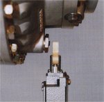
(In some of the illustrations the required guards are removed to improve visibility.)
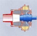
Foettinger's concept - Design and function
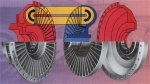
The Voith Turbo Coupling is a hydrodynamic coupling based on Foettinger's Principle. Its main components are two bladed wheels - a pump wheel and a turbine wheel - as well as an outer shell. Both wheels are positioned relative to each other. Output is achieved with minimal mechanical wear and there is no mechanical contact between power-transmitting parts.
The coupling contains a constant quantity of operating fluid, usually mineral oil.
The torque transmitted by the drive motor is converted into kinetic energy of the operating fluid in the pump wheel to which the motor is connected. In the turbine wheel, this kinetic energy is converted back into mechanical energy. When it comes to the function of the coupling, three modes are to be noted:
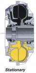 |
Stationary All operating fluid in the coupling is static. |
 |
Starting
The pump-wheel accelerates the operating fluid as revolutions in the drive-motor increase, so that a circular current of fluid is created in the working chamber. The entire bladed surface of the turbine wheel is impacted and thus set in motion through kinetic energy. The torque development during the starting procedure is indicated by the characteristic curve of the coupling. |
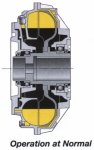 |
Operation at Normal Rating Owing to the minimal difference in speed between the pump and turbine wheel, a constant flow is achieved in the coupling. Only the demand torque from the machine is transmitted. Through skilful coordination of compensating chambers, such as the delay chamber and the annular chamber shell, the starting performance of the Turbo Coupling can be regulated (see characteristic curves on page 4). |
A suitable coupling for any drive
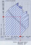
Essential design factors for a coupling are the power and speed of the drive motor.
Having established the nominal power and speed required, the diagram on the right enables determination of the appropriate size of the coupling.
Different conditions require different starting procedures (characteristic curve) for the coupling. Important criteria in this respect are the mass moment of inertia, torque limitation and frequency of start-ups.
In the table below different types of couplings and their starting conditions are compared.
![]()
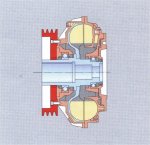
The basic type - Turbo Coupling "Type T"
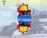
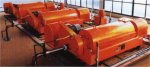
Turbo Coupling Type T is the basic version of constant-fill couplings, consisting of pump wheel, turbine wheel and outer shell.
A further range has been created by the addition of other parts to this basic type.
The turbo coupling is normally mounted on the machine shaft or gearbox shaft to be driven (outer wheel drive). In order to compensate for any slight installation inaccuracies, a flexible connecting coupling is used to join coupling and input shaft.
Installation of this type of coupling is recommended when vibration and overload protection are required for motor and machine; they may also be used for simpler transmission systems in the lower performance range.
Applications:
Bucket-wheel equipment
Excavators
Mixing, kneading and stirring machines
max |
max |
max |
||||||
|
1Weight with connecting coupling and max oil filling. |
||||||||
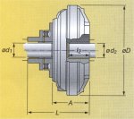
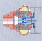
Smoother start up - Turbo Coupling "Type TV" and "TVV"
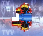
This version features a ,,delay-fill chamber" which is flange-connected to the outer wheel of the coupling (Type TV). At stand-still, a proportion of the working fluid lies in this chamber, thus reducing the volume in the working chamber. Hence on motor start-up, a reduced coupling torque is transmitted, whilst simultaneously providing an unloaded motor start. After the motor has run up, the working fluid flows from the delay-fill chamber into the working chamber which smoothly accelerates the driven machine up to its operating speed.
Furthermore, if the application so demands, the delay-fill chamber can be further enlarged (Type TVV), thus enhancing its effects and further reducing the coupling torque on motor start, as well as resulting in even longer and smoother start up of the driven machine.
In certain cases, the function of the delay chamber can be additionally improved through centrifugally controlled valves (Type TVF) or through hydrodynamic refill (Type TVY).
Applications:
Belt conveyors
Chain conveyors
Centrifuges, decanters
Tube Mills
High-inertia machines
Size Type A D L
maxd1
maxd2
maxl2 Weight Kg1 274 TV 172 328 328 65 55 90 32 274 TVV 204 328 360 65 55 90 33 274 DTV 244 328 403 65 55 105 38 366 TV 225 424 384 75 65 120 56 366 TVV 295.5 454.5 75 65 120 58 422 TV 257 470 430 90 80 135 80 422 TVV 335 508 90 80 135 83 487 TV 297 556 487 100 90 155 111 487 TVV 382 572 100 90 155 119 562 TV 333 634 554 120 110 170 172 562 TVV 428 649 120 110 170 182 650 TV 384 740 658 140 120 200 262 650 TVV 494 768 140 120 200 278 750 TV 440 842 603 140 135 240 390 750 TVV 567 730 140 135 240 408 866 TV 493 978 682 160 150 265 570 866 TVV 641 830 160 150 265 595 1000 TV 547 1118 757 180 160 280 870 1000 TVV 686 896 180 160 280 908 1150 TV 670 1295 880 180 180 320 1235 1150 TVV 883 1093 180 180 320 1289 1Weight with connecting coupling and max oil filling.
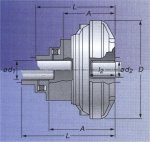
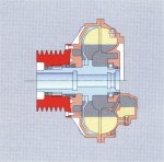
The innovative one - Turbo Coupling "Type TVVS"
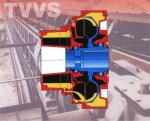
A further Voith development is the annular-chamber shell additional to the enlarged delay chamber (Type TVVS).
The additional chamber in the coupling shell enables further reduction of the starting torque. During the initial rotations of the start-up procedure, centrifugal forces normally cause the outer chamber of the coupling to be completely filled with operating fluid from the bladed area.
In comparison with couplings without annular chamber, filling of the bladed area of a TVVS Coupling is considerably slowed down, which, in turn, reduces the torque transmitted during motor run-up.
The increase in torque then follows through gradual emptying of the fluid from the delay chamber into the bladed area.
The starting procedure can be adapted to the requirements of the application by adjustable nozzle screws.
This new concept for couplings was designed especially for conveyor belt drives. Through the gradual build up of torque an automatic adaptation to belt load conditions is achieved.
Application:
Belt conveyors
Size Type A D L
maxd1
maxd2
maxl2 Weight Kg1 422 TVVS 335 470 508 90 80 135 87 487 TVVS 382 556 572 100 90 155 126 562 TVVS 428 655 649 120 110 170 192 650 TVVS 494 756 768 140 120 200 294 750 TVVS 567 872 730 140 135 240 425 866 TVVS 636 1012 825 160 150 265 645 1Weight with connecting coupling and max oil filling.
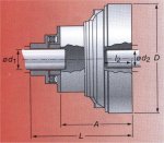
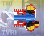
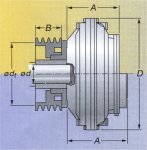
For pulley drives -Turbo Coupling "Type TRI / TVRI"
The vee-belt or flat belt pulley which is flanged to the bearing cover allows various transmission ratios to be accommodated. If required, the pulley may be easily exchanged.
TRI and TVRI type Turbo Couplings are normally installed on the motor shaft in an overhung position. The belt force is supported by a bearing in the bearing cover on the coupling hub.
TRI type Turbo Couplings can be installed both as starting aid and overload protection. Type TVRI with additional delay chamber is recommended if a particularly smooth start-up is required.
Applications:
Centrifuges and decanters
Fans
Mixers
Crushers
|
B |
max |
max |
kg1 |
||||
| 206 | TRI | 97 | 248 | 70 | 116 | 42 | 9,5 |
| 206 | DTRI | 137 | 248 | 70 | 116 | 42 | 12,5 |
| 274 | TRI | 137 | 328 | 100 | 150 | 55 | 25 |
| 274 | TVRI | 172 | 328 | 100 | 150 | 55 | 28,5 |
| 274 | DTRI | 175 | 328 | 135 | 165 | 60 | 33 |
| 274 | DTVRI | 242 | 328 | 135 | 165 | 60 | 38 |
| 366 | TRI | 198 | 424 | 145 | 160 | 65 | 42 |
| 366 | TVRI | 255 | 424 | 145 | 160 | 65 | 49 |
| 422 | TRI | 205 | 470 | 160 | 182 | 70 | 65 |
| 422 | TVRI | 257,5 | 470 | 160 | 182 | 70 | 71 |
| 487 | TRI | 246 | 556 | 201 | 233 | 90 | 99 |
| 487 | TVRI | 297 | 556 | 201 | 233 | 90 | 109 |
| 562 | TRI | 269 | 634 | 294 | 265 | 100 | 162 |
| 562 | TVRI | 333 | 634 | 294 | 265 | 100 | 174 |
| 650 | TRI | 317 | 740 | -- | 423 | 105 | 228 |
| 650 | TVRI | 384 | 740 | -- | 423 | 105 | 246 |
|
1Weight with max oil filling without pulley. |
|||||||
Monitoring devices and accessories
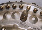
MTS mechanical thermal switches
As protection against overheating, fusible plugs are a standard fitment.
In order to avoid loss of operating fluid through thermal overload, a mechanical thermal switch - MTS - can be added.
On achieving the response temperature, the element activates a pin which then operates a switch.
Depending on the type of circuit, the signal can be used either as an alarm or to switch off the motor.
The circuit element has to be replaced after activation.
BTS - Non-contact thermal switch
Monitoring of coupling temperatures takes place without any contact. After activation of the switch, no replacement of the element is required. It is ready for use as soon as the coupling has cooled down.
The signal can be used either as an alarm or to switch off the motor.
In some cases BTS can be used as speed monitor.
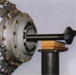
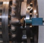
Fitting and dismantling tool
Required for professional, safe fitting and dismantling.
As well as the mechanical fitting and dismantling tool, a hydraulic pressure device is available.
Sight glass
By fitting a sight glass, the fluid level in the coupling can be easily checked without opening the coupling.
For special applications -Additional types
In order to provide solutions for an ever greater variety of applications, our engineers and technicians have developed additional types of constant-fill couplings.
Turbo Coupling with solid shaft and primary coupling flange
The coupling is fitted rigid to the motor shaft over a primary coupling flange. The weight of the coupling is thus carried by the motor shaft and the load on the drive shaft is relieved.
An elastic connecting coupling is required between the solid shaft on the output side and the driven shaft.
By using a specially designed flexible connecting coupling it is possible to fit or dismantle the coupling radially without moving motor or gears.
Turbo coupling with brake flange
For use with a breaking system, the turbo coupling can be equipped with an additional brake flange to which a brake-drum or brake-disc is fitted.

Turbo coupling with twin circuit "Type DT"
This coupling has two co-axial work circuits operating in parallel.
By means of a double circuit the output of the same size coupling is effectively doubled.
The properties, such as starting and overload protection are comparable with those of basic Type T without delay chamber.
For available sizes of Turbo Coupling Type DI see performance characteristic diagram on page 4.
Pulley-type coupling without bearing cover Type TRI
This type is ideally suited for particularly small belt discs.
The pulley with integral bearing is flanged directly to the coupling shell.
Subsequent replacement of the belt disc would be costly.
Turbo Coupling with overhung pulley installation - Type TR
In this simplified version of the pulley coupling, the pulley is fitted to the coupling shell in an overhung fashion.
Turbo Coupling TR is an economical solution for applications in the lower power range.
Competence in hydrodynamic drive technology
Modern drive concepts demand state-of-the-art technology, hence Voith drives are present where exacting performance is demanded.
Decades of experience in the field of hydrodynamics, continuous research and development, state-of-the-art production technology and the Voith know-how guarantee the quality of our product and keep it at the fore-front of technological development.
Our quality is certified under the code DIN ISO 9001.
Our engineers with their specialized product knowledge are at your disposal to provide the optimum drive solution for your applications.
Marketing companies and sales agencies in every continent ensure close contact with our customers and guarantee rapid service.
ESPRIT, EXCELLENCE and EFFIZIENZ together symbolize the factors through which concepts are born and products created within the Voith Group.
ESPRIT - researching and developing in the service of the customer.
EXCELLENCE - staying ahead of the field.
EFFIZIENZ - transforming individual achievement into corporate success. For our customers. For our staff. For our company.
![]()