|
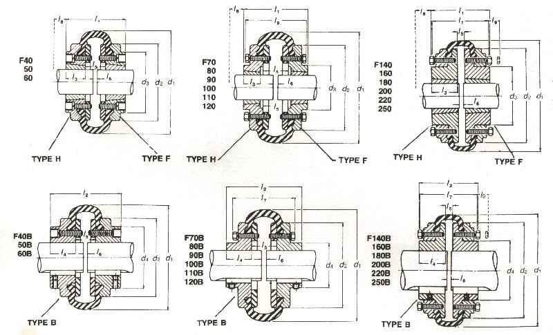
Taper-Lock |
Bored to size |
d1 |
d2 |
d3 |
d4 |
l1 |
l2 |
l3 |
l4 |
+ l5 |
l7 |
* l8 |
l9 |
Max rpm |
Torque |
Torsional Stiffness N.m/ # |
Max Misalignment |
Approx total mass (kg) |
||||||
|
Coupling Size |
Bush No. |
Max Bore |
Coupling Size |
Max Bore |
Min Bore |
Normal |
Max |
Parallel |
End Float |
|||||||||||||||
|
F40 |
1008 |
25 |
F4OB |
32 |
13 |
105 |
82 |
- |
- |
66 |
66 |
22 |
22 |
22 |
- |
29 |
- |
4500 |
24 |
64 |
5 |
1,1 |
1,3 |
2,3 |
|
F50 |
1210 |
32 |
F50B |
38 |
19 |
133 |
100 |
79 |
79 |
75 |
89 |
25 |
32 |
25 |
- |
38 |
- |
4500 |
66 |
160 |
13 |
1,3 |
1,7 |
2,7 |
|
F60 |
1610 |
42 |
F6OB |
45 |
19 |
165 |
125 |
103 |
70 |
83 |
109 |
25 |
38 |
33 |
- |
38 |
- |
4000 |
129 |
318 |
26 |
1,6 |
2,0 |
5,1 |
|
F70 |
1610 |
42 |
F7OB |
50 |
19 |
187 |
144 |
76 |
76 |
100 |
130 |
25 |
45 |
40 |
99 |
38 |
- |
3600 |
203 |
487 |
41 |
1,9 |
2,3 |
6,3 |
|
F80 |
2012 |
50 |
F8OB |
65 |
25 |
211 |
167 |
95 |
95 |
107 |
145 |
32 |
51 |
43 |
105 |
42 |
- |
3100 |
316 |
759 |
63 |
2,1 |
2,6 |
9,4 |
|
F90 |
2517 |
60 |
F9OB |
76 |
32 |
235 |
188 |
111 |
111 |
136 |
160 |
45 |
57 |
46 |
118 |
48 |
- |
3000 |
456 |
1096 |
91 |
2.4 |
3,0 |
14,1 |
|
F100 |
2517 |
60 |
F100B |
85 |
32 |
254 |
216 |
124 |
124 |
138 |
168 |
45 |
60 |
48 |
122 |
48 |
- |
2600 |
606 |
1517 |
126 |
2,6 |
3,3 |
20,1 |
|
F110 |
2517 |
60 |
F11OB |
90 |
32 |
279 |
233 |
140 |
140 |
135 |
175 |
45 |
65 |
45 |
125 |
48 |
- |
2300 |
855 |
2137 |
178 |
2,9 |
3,7 |
26,4 |
|
F120 |
3020 |
75 |
F12OB |
102 |
38 |
314 |
264 |
152 |
152 |
151 |
201 |
51 |
76 |
49 |
141 |
54 |
- |
2050 |
1183 |
3547 |
296 |
3,2 |
4,0 |
36,7 |
|
F140 |
3535 |
90 |
F14OB |
127 |
76 |
359 |
311 |
195 |
195 |
203 |
203 |
89 |
89 |
25 |
171 |
67 |
14 |
1800 |
2070 |
5642 |
470 |
3,7 |
4,6 |
70,6 |
|
F160 |
4040 |
100 |
F16OB |
140 |
89 |
402 |
346 |
216 |
216 |
226 |
226 |
102 |
102 |
22 |
183 |
80 |
15 |
1600 |
3425 |
9339 |
778 |
4,2 |
5,3 |
96,8 |
|
F180 |
4545 |
110 |
F18OB |
165 |
68 |
470 |
394 |
252 |
252 |
261 |
261 |
114 |
114 |
33 |
208 |
89 |
16 |
1500 |
5700 |
16455 |
1371 |
4,8 |
6,0 |
139,7 |
|
F200 |
4545 |
110 |
F200B |
180 |
76 |
508 |
429 |
267 |
267 |
261 |
261 |
114 |
114 |
33 |
256 |
89 |
16 |
1300 |
8620 |
23508 |
1959 |
5,3 |
6,6 |
190 |
|
F220 |
5050 |
125 |
F220B |
190 |
78 |
562 |
474 |
289 |
289 |
294 |
294 |
127 |
127 |
40 |
270 |
92 |
17 |
1100 |
11600 |
33125 |
2760 |
5,8 |
7,3 |
248 |
|
F250 |
5050 |
125 |
F250B |
220 |
88 |
628 |
532 |
310 |
310 |
300 |
354 |
127 |
154 |
46 |
300 |
92 |
18 |
1000 |
14675 |
42740 |
3562 |
6,6 |
8,2 |
309 |
All coupling sizes have an angular misalignment capacity up to 4.
# Coupling sizes F70 to F250 can be supplied with an alternative stiffness tyre depending on the nature of the duty.
All couplings have hexagon head bolts except sizes F40, F50, F60 which have cap head screws.
* l8 is the wrench clearance to allow for tightening and loosening the bush on the shaft. The use of a shortened wrench will allow this dimension to be reduced.
‡ l6 Shaft ends, although normally located distance l5 apart, can project beyond the flanges as shown. In this event, allow sufficient space between shaft ends for end float and misalignment.
+ l5 is the normal distance between flanges. End float which increases or decreases this distance by slight amounts is permissible.
l9 amount by which clamping screws need to be withdrawn to release tyre.
Maximum Torgue figures should be regarded as short duration OVERLOAD rating for use in such circumstances as direct on-line starting.
NOTE: FLANGES/CLAMPING RINGS STAMPED SIZE WITH SUFFIX 'M' ARE THREADED FOR METRIC FASTENERS E.G. F90 HM.