|
Extracts from a paper titled "Mathematical Selection Criteria
with particular reference to the influence of additional loads" |
|
Presented by Mr A. Frittella at Science Park Frankenwald South Africa 13th February 1991
INTRODUCTION
Idlers are considered the necessary evil of a conveyor system. Required in large numbers but
compared to all other conveyor components, they are relatively inexpensive.
As the idlers are required in large quantities, selection is usually based on price.
The idler is the component most likely to fail on a conveyor and together with a poorly designed
chute, will impart the most damage to a conveyor belt.
The table below indicates the bearings, used in the idler with the associated mayor dimensions and
design load ratings.
|
|
Shaft
Diameter
|
Bearing
Type
|
Dynamic Bearing
Rating
(N)
|
Wear
rating
(N)
|
Bearing
O.D.
(mm)
|
Bearing
Width
(mm)
|
|
20
|
6204
|
12700
|
0
|
|
|
|
25
|
6205
|
14000
|
28000
|
|
|
|
25
|
6305
|
22500
|
0
|
|
|
|
25
|
420205
|
0
|
0
|
|
|
|
30
|
6206
|
19500
|
0
|
|
|
|
30
|
6306
|
28100
|
0
|
|
|
|
30
|
420306
|
0
|
0
|
|
|
|
35
|
6307
|
33200
|
0
|
|
|
|
40
|
6308
|
41000
|
0
|
|
|
|
50
|
6310
|
61800
|
0
|
|
|
|
60
|
6312
|
81900
|
0
|
|
|
|
~
|
~
|
~
|
~
|
|
|
|
~
|
~
|
~
|
~
|
|
|
|
~
|
~
|
~
|
~
|
|
|
|
~
|
~
|
~
|
~
|
|
|
Requirement of an Idler
To support the load of material and belt throughout its length.
Considerations in Selection
- Diameter of roll
- Diameter of shaft
- Geometry of idler set
- Construction of shell
- Seal configuration
- Idler set life
- Power absorbed
Design Factors
Diameter of roll and shaft are inter-related in calculating an optimum idler design, because they
directly affect the bearing life. Therefore the initial criteria for selection will be :
A. Roll diameter
B. Bearing life
C. Shaft deflection
A. Roll diameter
The roll diameter has been generally ignored as the criteria for idler selection, where the
standard 127 mm diameter roll is used for most applications. However research by many organizations
has produced findings which suggest that the roll diameter has a major influence on power.
The table below shows the findings as published by Conveyor Dynamics Inc. on the effect of roll diameter on power absorbed
by a conveyor.
Rubber Indention Power Reduction : 1-(d1/d2)2/3 |
|
|
|
|
|
|
|
|
|
|
|
|
|
|
|
|
|
|
|
|
|
|
|
|
|
|
|
|
|
|
|
|
|
|
|
|
|
|
|
|
|
|
|
|
|
|
|
|
|
|
|
|
One can see that changing the roll diameter from 127mm to 152mm will reduce power by 13%.
B. Bearing Life
Bearing life has two common methods of calculation :
Firstly the B10 Selection Formula
B10=(C/(P/2))*(106/N/60)
B10= calculated life (Hours)
C = bearing dynamic load factor (N)
P = radial load on the roll (N)
N = bearing rotating speed (r.p.m.) = 60v(3.1416*D)
v = belt speed (m/s)
D= roll diameter (m)
The second method commonly used has been developed to reduce premature failure of bearings
generally caused by the bearing running in unclean conditions due to inefficient or worn seals.
This factor is not accounted for in the B10 life formula which assumes that the bearing is run
under optimum conditions.
S.K.F. (U.K.) in conjunction with the British National Coal Board developed a bearing, termed the "seize resistant" type, for use in idler rolls.
This bearing shows a marked improvement in performance over the standard deep groove ball bearing when operating in contaminated conditions with the mode of failure on this "seize resistant" type bearing being "wear" and not fatigue as evident on the standard ball bearing.
SKF have published an empirically determined formula for calculating the Effective Service Life (wear life) of its seize resistant bearings, as follows :-
Les=Lp*Sef*Sf
Where:-
Les = Effective Service Life (years)
Lp = Bearing Life, Initial stage prediction (years) = (RW/(P/2))2.5 / (0.522*N)
Rw = Bearing Wear Rating (N)
P = Load on the roll (N)
N = Bearing rotating speed (r.p.m.)
Sf = Service factor
Lrf = Life reduction factor
Sef = Seal efficiency factor
Table A : Sef ( Seal efficiency factor )
|
Most efficient sealing condition |
|
|
|
|
|
For shaft deflection >0.004 radians (13.75min) |
|
Seals with grease churning action |
Table B : Ef (Environmental factor)
|
Conveyors subjected to occasional flooding and concentrated
dust - underground mines |
|
Conveyors subjected to concentrated dust and rainfall - plant
conveyors |
|
Conveyors subjected to natural countryside dust and rainfall -
overland conveyors |
Table C : Uf (Usage factor)
Comparison between Bearing Life Formulas.
Graph below has been prepared to show variations in the effects of the bearing life
formulae.
In our example the Idler load P = 2442 N
The bearing used is a sieze resistant type 420205 with a dynamic load rating
C = 12700 N and a wear rating RW = 28000 N
The modification factors used in the calculation are : -
- Environmental Factor Ef = 0.11
- Usage Factor Uf = 1.0
- Seal Efficiency Factor Sef = 0.6
- The roll diameter used is 127 and 152mm
Graph showing the comparison betweeen the Bearing Life
Formulae :

Shaft Deflection
The acceptable shaft deflection is governed by the amount of deflection which the outer and inner
races of the bearing can be deflected without resulting in a substantial decrease in bearing
life. |
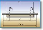 |
The formula used to calculate the angular deflection is :
Angular Deflection = Pcl/4EI*180*60/(π) (minutes)
Where :-
C = dimension from bearing to reaction point (m)
C = bearing centers (m)
l = modulus of elasticity (210 Gpa for steel)
I = moment of inertia of the shaft (m 4) = (π)d4/64
d = shaft diameter (m)
By substitution the formula may be simplified to :
Angular Deflection = (0.08373*P*c*l)/d4
Where the units of dimensions c, P and d are now in mm.
Thus the factors influencing shaft deflection are the shaft diameter and the distance between
bearing and support point.
Increasing the shaft diameter is the simplest method of reducing
deflection. An increase from 25mm to 30mm results in 51,8% decrease in angular deflection.
The distance between the support point and roller face is normally determined by applicable
specifications (e.g. SABS 1313) and the roll end design.
Thus the c dimension is largely dependant on the design of the sealing system utilised for bearing protection, and
should be minimized on the basis of allowing sufficient space for the installation of an efficient sealing
system.
The permissible angular misalignment between outer and inner races, which will not
produce inadmissably high additional stresses in the bearing depends on the radial internal
clearance of the bearing during operation, the bearing size, its internal design and the forces
and moments acting on it.
Bearing manufacturers quote the following limits:-
For design purposes some allowance has to be made for the possibility of the bearing being
installed in a slightly misaligned position and the following deflection limits are in general
use :
Deep Groove Ball Bearings 6 minutes
Seize Resistant Bearings 10 minutes
In Germany a deflection criterion of 15 minutes is used with Deep Groove Ball bearings of C4
internal clearance.
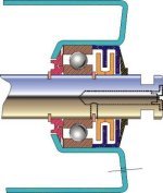
Effect of "c" Dimension :
As some form of sealing system is required 'c' dimensions below 35mm are not practically
achievable. The ranges normally used are between 40 and 60
Following is an example of a common seal arrangement with the limitations of the 'c' dimension. |
 |
Shell thickness to prevent buckling.
Standard pipe sizes for idlers are given in the table below.
|
Pipe Diameter
|
Wall Thickness
|
Spec
|
|
|
|
|
|
|
|
|
|
|
|
|
|
|
|
|
|
|
|
|
|
Thickness of bearing housing.
Bearing housings are generally pressed from 3mm plate into the correct shape however, there has been attempts to make cast iron and plastic end caps.
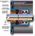
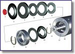
Connection of end disks.
The sketches below show four common connection details :
|
1. Plastic Grease Plug--Coloured for Grease Type, Year of manufacture
2. Weather Seal-- Non-Rubbing Water and Fire resistant
3.& 5. Outer Seal Components-- Multi-Labyrinth non-rubbing Close rubbing(Press fit seals)
4. & 6. Inner Seal Components
7. & 11. Circlip-- Locates Bearing on Shaft, One end only, Spring Steel Hardened and Tempered
8. Bearing-- Deep Groove Single Row Precision Ball or Spherical Roller Single Row C3 & C4 Clearance
9. & 10. Rear Seal Assembly--Combination pressed Metal/Plastic, Non-Rubbing Seal
12. Identification Slot
13. Shaft-- Ground Shaft Accurately Located Circlip Grooves
14. Shell & End, Deep Drawn Steel Pressing and Concentric Bearing Housing Bored with .001 Tolerance
15. Corner Radius-- Generous Radius on Corner of Roller, essential to protect Belt
16. Rigid Shell- Small Runout
17. Breather Hole
|
Calculation of the load on idler roll.
 |
Basic radial load.
a. The Mass of Material Transported.
b. The Mass of the Belt.
c. The Rotating Mass of the Rolls. |
a. Mass of Material
The load due to the mass of material is calculated from :
Wm=Qd/(3.6*v)
Where:-
Wm = mass of material (kg/m)
Qd = design throughput (t.p.h.)
v = belt speed (m/s)
b. Mass of the Belt
The load due to the belt sitting on the idlers is defined as : Wb (kg/m)
c. Rotating Mass of the Roll
The elements making up the total roll rotating mass are:-
Mass of shell
Mass of end discs
Discs
Mass of rotating bearing and seal elements and the load due to the rotating mass is defined as : Wr
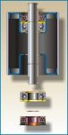
Load Sharing
In general one has a multi roller situation in a conveyor idler with the load being apportioned amongst the rolls.
As illustrated in the sketch above, the centre roller in a trough idler configuration carries the greater proportion of the load and the roll selection is based on the design results obtained for the centre roll.
For highly loaded, large diameter heavy wall idlers the axial thrust on the wing rolls will also
be a factor and must be analysed.
When calculating the Material load effect on each roll, consideration must be given to the comparitive size of each roll.
In order to produce load sharing there has been a tendency to reduce the centre roll width in comparison to the wing rolls.
However generally a 66% load rating is used for the analysis.
On the return idlers the load due to the belt mass is shared between the 1st or 2nd rolls.
Total Basic Axial Load
Basic Axial Load acting on the roll :-
P1 = ((Pm*et+Pb*eb)*at+Pr)*9.81
P1=Basic axial load (N)
Pm = Load due to mass of material (kg/m)
et = 0.67 for 3 roll trough, 0.47 for 5 roll trough
Pb = Mass of belt (kg/m)
eb = (Lt+20)/Beltwidth(m)
Lt = Width of center roll (m)
at = Trough idler spacing (m)
Pr = Load due to rotating mass of idler (kg)
Additional Loads
Dynamic load factors
The formulae proposed are based on static design principles and some allowance for the dynamic
nature of the application has to be made. This is done by applying a dynamic load correction
factor which is dependant upon : - size and mass of transported material - type of idler mounting -
rigid or flexible - belt speed.
An empirically determined factor to be used for troughing idlers is :
t=1+Cav
t = dynamic load factor - trough side
v = belt velocity in m/sec
Ca = Factor allowing for type of material and type of idler support (see chart below)
|
|
|
|
|
|
|
|
|
Coarse chips on layer of cushioning material |
|
|
Coarse chips without layer of cushioning material |
|
|
Exclusively coarse lumps weighing up to 100kg |
|
|
The application of a dynamic load factor to the return idler is equally important. Belt vibrations
are substantially more pronounced on the return strand due to the relatively large idler spacing,
increased runout on the longer rolls and reduced dampening effect.
A factor which has been used successfully is :
t=1.4
Load due to convex curve
One of the readily recognised additional loads imposed on an
idler set is that due to the change in belt direction in a convex curve. |
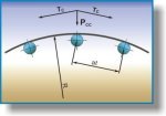 |
The additional load (on the centre roll) due to this change in direction is calculated as :
Pcc=(2*Tc*ac*eb)/R
Where :-
Pcc = Load due to convex curve (N)
Tc = Belt tension in curve area (N)
ac = Idler spacing in curve area (m)
R = radius of curve (m)
eb = (Lt+20)/Beltwidth(m)
Lt = Width of center roll
Load due to vertical misalignment :
A similar load due to the change in belt direction but not often considered, is that due to the
vertical misalignment of one idler with respect to the next.
 |
In general it would be realistic to assume that the vertical misalignment would result from the vertical misalignment of 2 adjacent support stringers (with a relatively small portion of this value being the result of manufacturing Tolerances.)
This situation is illustrated in the sketch about : |
The misalignment loads on individual rolls are determined by :-
Trough idler : Pmat=(T1y/at)*eb
Where:-
Pmat = trough side misalignment load (N)
T1 = trough side tension (N)
y = vertical misalignment (m)
at = trough idler spacing (m)
eb = (Lt+20)/Beltwidth(m)
Lt = Width of center roll
Return : Pmar = (2Ty/ar)*eb
Where Pmar = return side misalignment load (N)
Ty = return side tension (N)
ar = return idler spacing (m)
eb = (Lt+20)/Beltwidth(m)
Lt = Width of center roll
The misalignment load becomes particularly significant under conditions of high tension, (very long overland or high lift
incline belts) and areas of large misalignment (such as in the adjustable type structure used in underground collieries where stringer misalignment of the order of 50mm are commonplace.)
Total Load on the Idler
Thus the total load on the most highly loaded roll is defined as :
(i) Trough idler : Pt = (Pm*et*t*Pb*eb)*at+Pr)*9.81+Pcc+pmat
(ii) Return idler : Pr = (Pb*er*r*ar+Pr)*9.81+pcc+Pmar
As installations become more sophisticated the influence of runout and out of balance forces
will need consideration.