|
Rapid Load Out Systems Past, Present and Future |
|
BATEMAN MATERIALS HANDLING LTD &
ELB CONTRACTING LTD
SYNOPSIS
The paper traces the evolution and development of rapid train loading, it concentrates primarily on the rapid loading of coal and therefore with particular reference to the Richard's Bay Coal line. The loading of other materials is also discussed in order to bring into context the current state of the technology. The paper closes with predictions for the future development of rapid loading.
INTRODUCTION
In 1804 Richard Trevithick introduced the world to the steam driven railway engine, and almost immediately rail was recognised as a mass transport system. This was dramatically underlined in the late 1800's as the then coal capital of the world, South Wales, switched from canal transport to rail. Rail lines spread out rapidly from the major coal ports of Newport, Cardiff and Barry.
It was at this time that it became necessary to load coal into trains and of course the method of the day was to load them by hand.
A loading rate of maybe 2 tonne per man hour being average and hence the ten tonne rail wagons of the day were invariably loaded by large teams of 14 men. Loading into static trains of wagons is a far cry from today's loading rates which can be as high as 7 000 tonnes per hour all done by one man from his control desk.
1. EARLY DAYS
As mentioned coal wagons were loaded by hand from a coal pile which lay parallel to the rail line on which the train would be parked until full.
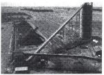
The next development was to form the coal pile above the level of the rail wagons and to face it with incline wooden chutes, one per wagon. Coal was then hand lashed down these chutes into the wagon.
Such crude methods of loading paid no heed to speed or mass accuracy.
One must remember that mechanisation as we know it only came into being in the 1950's and 1960's.
Materials other than coal were now being moved, materials such as iron ore and maize being good examples.
Maize loading was and is done from storage silo's into static railwagons.
Iron ore for example was loaded into slow moving rail wagons with the span of wagons being moved by a winch drawn rope.
One method of loading utilising this method can be seen at lscor's Thabazimbi mine where an ore bin feeds onto a horizontal conveyor belt which is situated above and along the line of wagons and feeds into them individually by means of a moving head.
Another interesting innovation was used at Douglas Colliery old coal plant where a bin feeds coal onto a conveyor situated above and along the line of wagons. The span of wagons moves below the conveyor, pulled by a winch, and when the end of each filled wagon is reached the conveyor is elevated, by means of a counter weight, preventing coal from being deposited between wagons.
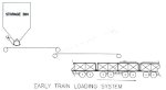
Figure 1
2. THE BEGINNING OF RAPID LOADING
The late 60's and early 70's saw the birth of dedicated or limited access rail lines. Typified by-lines such as Hammersly Iron in Australia and of course the Sishen Saidanha line, by their very natures they required improved methods of loading their trains. Operators of such lines had by now evaluated the requirements of a loading system and arrived at the following criteria:
-
A unit train of a fixed number identical rail wagons.
-
Sufficient material available to ensure that the unit train can be supplied.
-
A loading system which is reliable, accurate and sufficiently rapid to load the train in a specified time.
-
A device to move the train being loaded in an allotted time, through the loadout station.
The major components of a rapid loadout station are thus:
-
Storage
-
Loading
-
Train moving
-
Reliability
In addition, there are other important secondary components, such as records and sampling.
3. THE FLOOD SYSTEM
Incidentally not all of these components exist on all dedicated lines even today.
The obvious answer was to build a silo that would contain the same tonnage as the unit train, to move the train below the silo without stopping and to fill the wagon until it was full. Measurement of its contents could be done using a weigh bridge. This is essentially the "flood" loading or volumetric system.
In flood loading, the height of the material in the wagon is set by the position of the profile chute. the discharge gate is opened and closed by photocells monitoring the position of the wagon through the station. Two in-motion scales (IMS) are installed, one before the station and one after the station. These record the tare and the gross mass of the wagon, and the difference computed is the mass of material that has been loaded into the wagon.
The tare mass is fed to the control computer, as is the gross mass of the loaded truck passing over the second IMS. Using this information, the computer changes the height of the profile chute to compensate for over- and underloading. Essentially this method entails a gate below the silo opening and allowing material to flow into the wagon. Flow continues until the coal ceases to flow, this condition is termed "choke".
At this point the gate closes and the volume of coal left between the gate and the wagon, is contained in the profile chute from where it flows into the wagon as it moves below the profile chute. All calculations are dependant on volume and not mass.
Early flood stations were manually operated and, consequently, were relatively simple resulting in low capital costs. In order to meet the increased loading rates necessary for the new higher-capacity trains and in trying to improve the accuracy of loading, modern flood stations have to be equipped with sophisticated control automation. There is very little capital cost difference between a fully automated flood and a fully automated flask loadout today, while the flask remains a far more accurate system.
It is not possible to install an in-motion scale closer than three wagons from the loadout, and a major shortcoming of flood loading is that the mass reported to the control system does not relate to the wagon being loaded, but to a previously loaded wagon. This delay in reporting has a serious detrimental effect on the accuracy of loading, as there are many variables affecting the volumetric capacity, such as:-
-
bulk density
-
wagon suspension
-
wagon conditioning (side bulging)
-
delay in 3 wagon length
The most important difference is that in the flood system the mass of material is only measured after it is loaded into the wagon.
Flood loading systems predominate in most countries around the world, with the exception being South Africa.
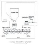
Figure 2
4. THE FLASK SYSTEM
The "Flask" loading principal stems, I believe from underground skip loading. This method is used on most underground mines and was devised initially as follows:- a horizontal conveyor feeds ore into a "dummy skip". This was filled during the time that the true skip was being hoisted, tipped on surface and lowered down the shaft. Thus once the empty skip was in position at shaft bottom the dummy skip quickly loaded it with an equal volume of ore and the cycle was repeated. By means of this batch method shaft cycle time was reduced to a minimum. So effective was this method that it is still in use today.
A "flask" mounted below the silo is loaded with the material and emptied into the wagon once the wagon passes below it. Obviously the timing of filling and emptying of the flask determines the train speed, and originally flasks were designed to hold the same volume as the wagon being loaded.
It soon became obvious that the capital cost of weighbridges could be greatly reduced if the flask and its contents were weighed by a balance beam system and this method was rapidly perfected. Train speed was however still a problem.
The first attempts to solve this was the so called twin flask method. Here the silo fed alternately into two flasks so that while one loaded a wagon the other was being filled. Two such systems were installed at lscor Sishen complex in 1972 and also at Van Dyks Drift and Landau Collieries in 1975.
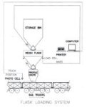
Figure 3
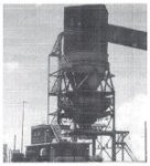
5. A MODERN FLASK
A modern flask loadout station comprises a bin or silo, a weigh flask (mounted on an assized load cell system), a profile chute and a control system. The set mass is reached the bingate closes.
As the wagon passes through the station, the weigh flask gate is opened and closed at the appropriate positions by photocell switches. The mass of material is therefore measured before it is loaded into the wagon. The computer programme has a "learning" capability and can change the set point while loading to ensure that the gross train mass is as close as possible to the desired load. At the same time it ensures that individual wagons are neither over- nor underloaded. The train payloads are commonly accurate to within 0.01 % and the cycle time for loading a wagon can be less than 60 secs for an 84 tonne wagon.
The predictable material flow is an important feature of a successful loadout station. Bin geometry and the size and shape of each loadout station storage bin or silo are finalised after material flow tests have been carried out and the particular material properties have been determined. In addition to the obvious benefits of regular material flow, a proper silo or bin cone geometry can result in significant savings due to a reduced overall height and the elimination of liners. The latter are not needed because, with the expanded flow technique, a central core of material is withdrawn first and material against the wall then migrates away from the sidewall towards the centre.
6. LOAD OUT SYSTEM SILO'S
Two schools of thought prevail on the size of bins and silos.
The first maintains that the load out system silo must contain sufficient material to load the full train, say 10 000 tonnes, while the second maintains that the silo should be the smallest possible say 300 tonnes.
6.1 Large capacity silos.
On newer mines, having been planned from outset to load for export, large-capacity (100 000 t) open stockpiles served by rail-mounted stackers and reclaimers have found favour.
Many operators select this option for the added security of knowing beforehand that the complete train load is already above the train and the chances of an unsuccessful loading are considerably reduced.
Thus whilst modern train loading rates of say 5 000 tph are commonly achieved it is only necessary to reclaim coal from the stockpile at a rate, dictated by the interval between trains, in the order of 1 200 to 1 500 tph.
|
Figure 4 |
Figure 4a |
6.2 Small capacity silos.
Loadouts having a relatively small "over-the-rail" bin capacity, say, 250 to 300 t, usually have smaller storage capacities, say, up to 25 000 t.
This system relies on a predictable and constant flow of material to the loadout station and careful attention has to be paid to this area. The reclaim system and the conveyor linking the withdrawal point to the loadout are high-volume units (capable of delivering at the same rate as the train is loaded say 5 000 tph) and critical to the successful loading of the train.
|
Figure 5 |
Figure 5a |
7. TRAIN MOVING
The loadout stations described above are designed for continuous loading. Accuracy of loading requires that trains are moved through the loadout at constant speed. SATS did not allow their main line locomotives to be used during loading operations, and, consequently, operators had to supply a suitable train mover.
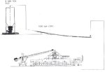
The moving force necessary to move a fully loaded train of 84 tonne wagons is high., and the typical required train speed was 8 to 20 m/min. While earlier loadout stations have used "main" and "tail" winches and shunting locomotives for train moving, modern stations install specially developed static or mobile train pushers
The wall-mounted hydraulic trainpusher is the most popular static unit. It utilises a substantial concrete wall built adjacent to the rail line, onto it are mounted two hydraulic cylinders, one above the other. Each of these cylinders has a push rod assembly, attached to the rod end, located by guide rollers so that it can be reciprocated in the horizontal plane. Each push rod has two sets of hydraulically activated "dogs". Wagons are equipped with pushing plates, which are engaged by the dogs. The cylinders extend and retract sequentially so that at least one dog is in contact with the pushing plate whilst the train is being pushed through the load out station. This type of train pusher is popular because of its simplicity, reliability and ease of automation.
Where more flexibility is required, for example, where there is a good possibility that a second load out station may be installed at the terminal at a later date, mobile locomotive type train pushers are used. These are sometimes referred to as robots, because they are fully automated and can be remote-controlled. Conventional wheel-driven robots are installed at a number of stations. A disadvantage of this type of machine is the multiplicity of axles required to comply with any maximum permitted axle load, resulting in a costly machine with complex drive arrangements.
To overcome this problem, a unique South African mobile trainpusher was developed. The Elbram, is a four-wheel, two-axle robot. The pushing force to move the 10 000 tonne train is provided by two hydraulic cylinders, pivot-attached to the underside of the chassis.
The cylinders are parallel to each other, with one set above each rail and in line with the latter. The rod end of each cylinder is fitted with a rail clamp assembly which, when not clamped, is trailed on the rail. In operation, one rail clamp is activated and the relative cylinder is extended moving the Elbram and, of course, the train. The other rail clamp being trailed. Near the end of the stroke of the first cylinder, the second clamp is activated the second cylinder pushes in unison with the first until the clamp on the latter is released the cylinder retracts, pulling the clamp up in preparation for the next pushing stroke. In transfer mode, both rams can be lifted from the rail and locked under the chassis. In this mode, the unit is driven by its hydraulic wheel motors.
8. WAGONS
As previously mentioned dedicated lines normally use a single wagon type, but as wagon sizes have increased, such as on the RBCT line, it is common to have train consists made up of only one size of wagon, rather than to mix wagon sizes in the train. However as will be described later in this paper, there are lines which utilise several different sizes of wagon and these may be randomly placed in the consist. This practice in the past favoured the use of the flood system since this system, as we have seen, filled wagons purely on volume. But not even the flood system cannot cater for too wide a range of wagon sizes and much spillage can occur..
Similarly the method of emptying wagons has an effect on their rapid loading. Tippler systems are best suited for fast effective loading, since bottom and side discharge wagons can cause delays if discharge doors open during loading. In such cases it is normal to find a spillage pit below the load out station that is capable of holding a full wagon loading. Cleaning of it being usually achieved by ramp and front end loader.
9. THE RBCT LINE AS IT WAS
The majority of South African coal mines producing steam coal for export are located well inland on the Highveld of the Transvaal. It was recognised right from the early planning stages of the export coal industry that, while the pithead price of producing coal was relatively low, transport costs to far- off world markets would be significant. To keep these costs as low as possible, a high capacity, highly efficient coal handling infrastructure comprising inland rapid train loading stations at producing mines, a 580 km long dedicated export coal unit train rail line and a massive port storage and loading facility at Richard's Bay was developed.
The first export train on the "coal" line transported 2 700 tonnes to Richard's Bay in January 1976, and during that year the State railway, South African Transport Services (SATS), conveyed about 4,5 Mt. to Richard's Bay. By 1984, approximately 36 M tonnes of export coal were hauled along the line, in trains of 176 x 59 tonne payload wagon giving 10 500 tonnes of coal per train. Half trains, that is, 88 trucks, were loaded at each mine and formed into 176 truck trains at a SATS marshalling yard before departure.
Even greater demand resulted in the line being uprated to accept 26 t, axle loads, and a new wagon with a capacity of 84 tonne was introduced. With its tare mass of only 20 tonnes, this wagon has one of the highest load-to-tare ratio anywhere in the world for a coal wagon. With RBCT having a planned capacity of 60 Mt. trains now comprised 200 x 84-tonne wagons for a train payload of 16 800 tonnes of coal. Again, half trains of 100 wagons were loaded at each mine.
To ensure optimisation of the line and the rolling stock, SATS have from the beginning allowed the loading mine only four hours to load a 100 wagon train. With the 59 tonne wagons, the required loading rate is approximately 2 000 t/h (allowing 30 min of the cycle for removing SATS locomotives, attaching the train moving device and charging brakes).
An 84 tonne wagon train, required a loading rate of 3 360 t/h.
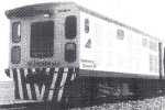
Figure 6
10. THE PRESENT
In the last two years there have been new technological improvements relating to computerised software, wagon identification, train movement and weighing systems.
Software is now based on Windows 95 and allows the operator to see the whole trainloading sequence of events take place on his screen as a real time graphic event. Similarly data relating to loading accuracy, number of wagons loaded, average loading time etc, is displayed.
My company has completed a load out station in England which loads two distinct limestone products into wagons ranging in size from 30 to 80 tonne. More importantly these can be randomly placed within the train. This technology entails storing each wagon types' "identity" in the PLC, and as the train enters the system the wagon is identified electronically. The PLC matches its data and "instructs" the flask to load the requisite number of tonnes.
We have extended this technology for a new load out station for Portnet which will handle a variety of products from coking coal to Sulphur and will load randomly sized wagons. A further advance here is the requirement clean the system between products. Another of our current contracts entails loading coal into random sized wagons randomly placed in the train and here the railway operating company was anti flask and favoured flood.
Their reason was that since the flask system loaded predetermined mass of coal into the wagon, should there be any carry over in the wagon then spillage will occur. By placing an in motion weigh system in front of the loadout station each wagon is weighed and its weight is checked against that wagon's identity in the PLC. Any overweight is deducted from the set point for the flask and effectively that wagon is underloaded. The mass of coal in the wagon is therefore the combined mass of carryback plus loaded tons. The printout identifies that wagon and lists the carry back tonnage. In a flood system the mine would have been paying for all carry back tonnes.
A similar system of pre-weighing wagons has been installed locally by one of our competitors to ascertain differences in tare mass and to then adjust loaded mass accordingly.
Locally the available methods of moving trains through an RBCT line load out station has undergone a dramatic change. Spoornet has developed a slow moving train system which allows the whole train to continue through the station without either stopping or uncoupling. Where the span of 100 wagons was originally left in the loop for four hours trains can now spend as little as two hours in the system when being loaded at 4 500 tph. Incidentally Canada, Australia and the USA have had slow moving loco's for some years.
Loadcell systems below the flask have always been assizable however recently these are being installed and assized, in some instances check assized systems are required and we are currently installing two such systems. These will allow the operator to call up the cheek weighing system which will verify the accuracy of the standard system. However since both systems are assized there is now the need to have both re-assized at regular intervals.
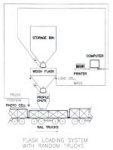
Figure 7
11. THE FUTURE
To predict the future we must examine the problems of both the railway operator and the loadout system operator.
Internationally railways are faced with increased demands on their lines and their rolling stock with the need to move more tonnage. One obvious method is to increase rolling stock but this increases costs and congestion.
The alternative is to increase wagon capacity, the United States for example between 1990 and 1994 average coal loads per wagon increased from 96,67 to 102,70 tonnes. The question is can the existing locomotives handle this increase, of for a 100 wagon train an additional 553 tonnes. Here again some lead can be seen in the USA where the gross train mass is being reduced by the introduction of Aluminium wagons which offer tare savings of between 10 and 12 %. They are also switching to AC locos which offer increased power and importantly the ability to use this power at the low speeds required during loading. This could also lead to an increase in the number of wagons in the train.
Spoornet have examined 100 tonne capacity wagons and eventually went the slow speed train route, which reduced turn around time. One estimate is that if all the load out stations on the RBCT line were to switch to this system it would be the equivalent of putting 1 000 extra wagons into use. They have also started to run, 102 wagon, trains having a total tonnage carrying capacity of 8 600 tonnes of coal per loadout station..
As to the load out systems themselves, here one can see a multiplicity of future changes.
Loading rates will increase in order to speed up cycle times and companies such as Spoornet will offer (as they are doing) reduced rates for faster turn around. We already have an RBCT station capable of loading at 5 200 tph or 1.65 hrs for an 8 600 tonne train. Our fastest station loads run of mine coal in excess of 7 000 tph or 30 secs for a 50 tonne wagon. However, beware, in this case the flask gate opens before the front of the wagon is below the profile chute!
Electronic wagon identification via some form of tag reader will simplify wagon identification and in turn improve wagon loading accuracy's. It will also simplify all data retrieval be it in the loading, transport or unloading phase.
Multi product loading on the same train will also become feasible because of such a system.
Already it is possible to receive wagon data electronically and to transmit it electronically and thus reduce the current use of hardcopy with its potential for errors. This linked to the above mentioned wagon identification system will together speed the departure of the load out control room from the station to the main mine control centre.
Environmental issues will also become prevalent. Such as noise, dust and appearance.
Look out also for containers being used for the rail transport of bulk materials. The shorthaul market in America already uses 100 tonne capacity flat top rail cars to carry four 25 tonne coal containers, referred to as "Coltainers".
If rail operators demand faster loading of coal and ore in order to contain and reduce costs the day cannot be far off when these demands are made of other bulk products such as maize and cement. These commodities will require much R & D since here we are talking, not of open top wagons but, of tanker systems. Compare the loading rates for coal with the recently published claim by an American engineering company for a system of loading borax into rail tank cars at the phenomenal rate of 15 minutes for a 100 tonne wagon-- 400 tonnes per hour no less!
12. CONCLUSION
A well-designed rapid load out system is one of the most trouble free plants in any mine system. Over 18 of my companies' systems in operation have produced only 2 call out breakdowns in the past 7 years and these include systems which have been in operation for almost 20 years.
The complexity and reliability of a modern rapid loadout system is not readily appreciated as is evidenced by the number of one off, reverse engineered systems, being installed.
The Research and Development required to provide future solutions is costly and as we have seen the thrust for continual development is as a result of demands made by railway operator. There is no real added value to the material supplier unless the railway operator provides sufficient incentive in the form of reduced rail tariffs for faster and more accurate loading of trains.
13. ACKNOWLEDGEMENTS
I wish to thank the Directors of Bateman Materials Handling Ltd for their permission to publish this paper and to those of the management and staff who assisted in its preparation.
BIBLIOGRAPHY
Anon
"Rail Transport System Report" World Coal February 1995.
J W Carson
"How to ensure Reliable Controlled Solids Flow at a Bulk Terminal" 4th Bulk Handling & Transport Conference 1983
W A H Deijs
"Design Analysis for Large Coal Storage Silos & Load - Out Stations in South Africa" Bulk Handling
W H Kerr
"Rapid Train Loading Practices at South African Export Coal Mines" Bulk Solids Handling August 1985
Dave Willis
"Rail Haulage Challenges in the Powder River Basin" Mining Engineering August 1994
CV of A.E.W. Fletcher
Eric Fletcher graduated from the Camborne School of Mines having previously worked on the mines in Ghana and South Africa. On returning to South Africa he rejoined on of the Major Mining Houses prior to moving into the field of Capital Equipment. He joined Batemans Materials Handling Ltd in 1991 as Marketing Manager and became the Marketing Manager of BMH-Brandt in 1996. He has published several papers on Mechanised Mining Equipment and Marketing.